MODEL 4DA35A/9102A 4DA36A/9106A
SPEED HIGH MED LOW HIGH MED LOW
CFM 930 780 620 1710 1500 1330
M
3
/s 0.43 0.37 0.29 0.80 0.71 0.63
RPM 1450 1300 1090 1545 1394 1244
Amps 0.40 0.30 0.27 0.71 0.54 0.48
Watts 39 35 32 77 65 57
dB (A) 45 41 36 53 49 44
FUNCIONAMIENTO
OSCILACIÓN VARIABLE: Jale la perilla de oscilación ubicada
en la parte posterior del motor hacia arriba. Gire el cabezal del
ventilador hacia la izquierda, derecha o hacia delante. Empuje la
perilla de oscilación hacia abajo y el ventilador oscilará describiendo el
ángulo jado.
ÁNGULO VERTICAL: Para ajustar el ángulo vertical, incline el cabezal
del ventilador hacia arriba o abajo, según preera.
VELOCIDAD: La velocidad está controlada por una perilla rotatoria:
(0) Apagado, (3) Alta, (2) Media, (1) Baja.
CABLE ELÉCTRICO: Enchufe el cable eléctrico en un tomacorriente
de pared (CA 120 Voltios, 60 Hz).
MANTENIMIENTO
ADVERTENCIA: SIEMPRE DESENCHUFE EL CABLE ANTES
DE MOVER O DAR SERVICIO AL VENTILADOR.
ADVERTENCIA: ¡NO SUMERJA EL VENTILADOR EN AGUA!
LIMPIEZA: Utilice un paño suave humedecido con una solución
jabonosa liviana, tal como un detergente líquido para lavar platos.
Seque TODAS LAS PARTES POR COMPLETO antes de rearmar.
Después de dar mantenimiento o servicio, REARME POR COMPLETO
la unidad en la forma descrita en este manual de instrucciones, antes
de volver a conectarla a la fuente de poder.
PRECAUCIÓN: No utilice gasolina, bencina, acetona,
limpiadores abrasivos, etc. puesto que dañarán el Ventilador.
NUNCA use ALCOHOL O SOLVENTES.
LUBRICACIÓN: Los cojinetes de precisión vienen sellados de por
vida en la fábrica y no precisarán ninguna lubricación adicional.
ALMACENAMIENTO: Guarde el Ventilador con estas instrucciones
en un lugar fresco y seco.
LISTA DE REPUESTOS
NO. DE PARTE PARA EL MODELO
REF DESCRIPCIÓN
4DA35A/9102A 4DA36A/9106A
CANT.
1 Motor 02030062GL 02030066GL 1
2 Cubierta del motor (frontal) 2010710 2010710 1
3 Cubierta del motor (trasera) 2010661 2010661 1
4 Tornillo Phillips reforzado 02090040 02090040 1
# 7 x 7/16
5 Botón de oscilación 2010119 2010119 1
6 Interruptor 02055087 02055087 1
7 Enlace de oscilación 2010276 2010276 1
8 Conector de alambre 2090529 2090529 1
9 Tornillo de enlace 02090140 02090140 2
10 Cuello 2010285 2010285 1
11 Perno de sujeción 02090516 02090516 1
12 Resorte de elevación — 02090586 1
13 Placa de trinquete 02010162B 02010162B 1
14 Eje de elevación 2090521 2090521 1
15 Tuerca hexagonal de 5/16-24 02090033 02090033 1
16 Base 2010540P 2010541 1
17 Perilla del Interruptor 2010131 2010131 1
18 Placa inferior 2010312 2010316 1
19 Cordón eléctrico con clavija 02050009AWFPC 02050009AWFPC 1
20 Rejilla frontal 02096217 02096214I 1
21 Tapa 2010058 2010059 1
22 Aspa 2010008 2011013 1
23 Tuerca de montaje de la rejilla 2010359 2010359 1
24 Rejilla plastica trasera 2011212 2011200M 1
25 Pata de caucho 2010415 2010415 2
26 Tornillo 2090038 2090038 1
27 Ornamento de la rejilla 02010381A 02010381A 1
28 Casquillo de cuello osc. 2010808 2010808 1
29 Tornillo #7 x .8 PPH 02090060 02090060 2
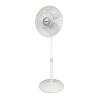
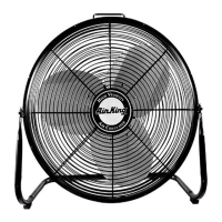
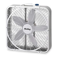
OSCILLATING FANS
12" (30.4 cm) MODEL 4DA35A/9102A
16" (40.6 cm) MODEL 4DA36A/9106A
SPECIFICATIONS
Motor ........................................120V, 60Hz (12")(30.4 cm)
120V, 60Hz (16")(40.6 cm)
Blade Size ................................12" (30.4 cm) Model(4DA35A/9102A)
16" (40.6 cm) Model(4DA36A/9106A)
Speeds .....................................3 Speeds
Control......................................Rotary Knob
Air Flow Distribution..................90°
4DA35A/9102A y 4DA36A/9106A
24
23
22
21*
21*
20
27
5
4
2
29
1
3
7
9
28
13
9
10
12
11
15
14
8
19
25
26
18
16
6
17
4. Para jar la Hélice, atornille el Girador en el Eje en el
Sentido Contrario a las Manecillas del Reloj hasta
que se encuentre ja en el cubo de la hélice.
5. Con el cabezal del ventilador en posición recta, alinee el Ornamento
de la Parrilla Anterior para que quede en posición horizontal. Inserte
la parte inferior de la Parrilla Anterior dentro de la Parrilla Plástica
Posterior. La Lengüeta en la parte inferior de la Parrilla Plástica
Posterior debería encajar entre los rayos de la Parrilla Anterior.
Encaje la Parrilla Anterior dentro de la Parrilla Plástica Posterior
comenzando desde arriba y progresando en forma descendiente
por ambos lados.
Clavija
Ranura
Figura 1
Figura 2
Figura 3
Motor
Tuerca de
Plástico
Hélice
Girador
Parrilla
Posterior
Parrilla
Posterior
Parrilla
Anterior
2084067
4
Rev. C 6/07
2084067
1
Rev. C 6/07
*NOTA: Se suministra 1 solo Tapa con el Ventilador.
ENSAMBLADO
1. Incline el cabezal del ventilador hacia atrás. Coloque la Parrilla
Plástica Posterior en el Motor. (Figura 1)
2. Alinee el corte triangular en “∆” en la Parrilla Plástica Posterior
con el poste triangular en la parte superior de la cubierta frontal del
Motor. Encaje totalmente la Parrilla Plástica Posterior y fíjela
con la Tuerca de Plástico, haciéndola girar en el Sentido de las
Manecillas del Reloj. (Figura 2)
3. Deslice la Hélice sobre el Eje del Motor. (Alinee la Ranura en el
bloque de la hélice con la Clavija del eje del motor.) (Figura 3)
GENERAL SAFETY INFORMATION
When using electrical appliances, basic
precautions should always be followed to
reduce the risk of re, electric shock and injury
to person, including the following:
1. Read all instructions before using Fan.
2. Make certain that the power source conforms to the electrical
requirements of the Fan.
3. Use this Fan only as described in this manual. Any other use
not recommended by the manufacturer may cause re, electrical
shock, or injury to persons.
4. Unplug power cord before installing, servicing, or moving the Fan.
WARNING: DO NOT DEPEND UPON THE ON-OFF SWITCH
AS THE SOLE MEANS OF DISCONNECTING POWER WHEN
INSTALLING OR SERVICING THE FAN. ALWAYS UNPLUG
THE POWER CORD.
5. This Fan must NOT be used in potentially dangerous
locations such as ammable, explosive, chemical-laden
or wet atmospheres.
6. DO NOT use Fan in or near a window. Rain may create an
electrical hazard.
7. The power cord is equipped with a three-prong grounded plug
that must be inserted into a matching receptacle. Under no
circumstances must the grounding prong be cut off the plug.
Where a two-prong wall receptacle is encountered, it must be
replaced with a properly grounded three-prong receptacle installed
in accordance with the National Electrical Code (NEC) and all
applicable local codes and ordinances. This work must be done
only by a qualied electrician, using copper wire only.
WARNING: USE OF A THREE-PRONG TO TWO-PRONG
ADAPTER IS NOT RECOMMENDED. IMPROPER CONNEC-
TION MAY CREATE THE RISK OF ELECTROCUTION. USE
OF SUCH ADAPTERS IS NOT PERMITTED IN CANADA.
WARNING: THIS PLUG IS A SAFETY FEATURE. TO
REDUCE THE RISK OF FIRE, ELECTRIC SHOCK AND
PERSONAL INJURY, DO NOT REMOVE, REPLACE, REPAIR
OR TAMPER WITH THE ORIGINALLY SUPPLIED PLUG. IF
THE FAN DOES NOT FUNCTION PROPERLY, IT MAY BE
DUE TO THE SAFETY DEVICE INCORPORATED IN THIS
PLUG. RETURN TO AN AUTHORIZED SERVICE CENTER
OR CALL 800-233-0268, MONDAY - FRIDAY, BETWEEN 8:00
AM AND 5:00 PM EST. IF THE PLUG WARNING LABEL IS
MISSING OR DAMAGED, CALL THE TOLL FREE NUMBER
FOR A REPLACEMENT LABEL.
8. Where possible, avoid the use of extension cords. If they must be
used, minimize the risk of overheating by ensuring that they are
UL listed. Never use a single extension cord to operate more than
one Fan.
9. DO NOT operate any Fan with a damaged cord or plug or after the
Fan malfunctions, has been dropped or damaged in any manner.
Return Fan to authorized service facility for examination, electrical
or mechanical adjustment or repair.
10.DO NOT insert or allow ngers or foreign objects to enter any
ventilation or exhaust opening as it may cause an electric shock
or re, or damage the Fan. DO NOT block or tamper with the Fan
in any manner while it is in operation.
11.Always place the Fan on a stable, at, level surface when operating,
to avoid the chance of the Fan overturning. Locate the Power
Cord so the Fan or other objects are not resting on it. DO NOT
run Power Cord under carpeting. DO NOT cover Power Cord with
throw rugs, runners, or the like. Arrange Power Cord away from
room trafc and where it will not be tripped over.
12.This Fan is NOT intended for use in wet or damp locations. Never
locate a Fan where it may fall into a bathtub or other water container.
13. DO NOT use Fan outdoors.
14.This Fan is NOT suitable for use in agricultural facilities including
areas where livestock, poultry or other animals are conned.
Please refer to National Electric Code (NEC) Article 547-7 (2002),
or applicable state or local codes or standards relating to electrical
requirements for Agricultural Buildings. THIS FAN DOES NOT MEET
THE REQUIRMENTS OF NEC ARTICLE 547-7 (2002).
15.This Fan is NOT suitable for use in hazardous locations. Please
refer to National Electric Code (NEC) Article 500 or applicable
state or local codes or standards relating to electrical requirements
for Hazardous locations. THIS FAN DOES NOT MEET THE
REQUIRMENTS OF NEC ARTICLES 500 (2002)
WARNING: REDUCE THE RISK OF FIRE OR ELECTRIC
SHOCK – DO NOT USE THIS FAN WITH ANY SOLID STATE
SPEED CONTROL DEVICES.
SAVE THESE INSTRUCTIONS
READ AND SAVE THESE INSTRUCTIONS
READ CAREFULLY BEFORE ATTEMPTING TO ASSEMBLE, INSTALL, OPERATE OR MAINTAIN THE PRODUCT DE-
SCRIBED. PROTECT YOURSELF AND OTHERS BY OBSERVING ALL SAFETY INFORMATION. FAILURE TO COMPLY
WITH INSTRUCTIONS COULD RESULT IN PERSONAL INJURY AND/OR PROPERTY DAMAGE!
RETAIN INSTRUCTIONS FOR FUTURE REFERENCE.
OPERATING INSTRUCTIONS & PARTS MANUAL
DESCRIPTION
The Air King 12" (30.4 cm) and 16" (40.6 cm) Oscillating Fans feature
whisper quiet operation with a 3 paddle blade. Fan is powered by a
pre-lubricated permanent split capacitor motor with a 6 ft. (1.8 m) 18/3
cord set. Fan grills meet OSHA requirements. UL listed.