Page 1
08/12
*2P0812*
507078−01
*P507078-01*
P.O. Box 799900, Dallas, TX 75379−9900
INSTALLATION INSTRUCTIONS
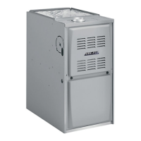
92AF1UH and 95AF1UH
Warm Air Gas Furnaces
Upflow/Horizontal Left and Right Air Discharge
This is a safety alert symbol and should never be ignored. When you see this symbol on labels or in
manuals, be alert to the potential for personal injury or death.
This manual must be left with the homeowner for future reference.
CAUTION
As with any mechanical equipment, personal injury
can result from contact with sharp sheet metal
edges. Be careful when you handle this equipment.
WARNING
Improper installation, adjustment, alteration, service
or maintenance can cause property damage, person-
al injury or loss of life. Installation and service must
be performed by a licensed professional installer (or
equivalent), service agency or the gas supplier.
Unit Dimensions 2. . . . . . . . . . . . . . . . . . . . . . . . . . . . . . . . .
92AF1UH/95AF1UH Gas Furnace 3. . . . . . . . . . . . . . . . . .
Shipping and Packing List 3. . . . . . . . . . . . . . . . . . . . . . . . .
Safety Information 3. . . . . . . . . . . . . . . . . . . . . . . . . . . . . . . .
Use of Furnace as a Construction Heater 4. . . . . . . . . . . .
General 5. . . . . . . . . . . . . . . . . . . . . . . . . . . . . . . . . . . . . . . . .
Combustion, Dilution, Ventilation Air 5. . . . . . . . . . . . . . . .
Setting Equipment 8. . . . . . . . . . . . . . . . . . . . . . . . . . . . . . . .
Filters 12. . . . . . . . . . . . . . . . . . . . . . . . . . . . . . . . . . . . . . . . . .
Duct System 12. . . . . . . . . . . . . . . . . . . . . . . . . . . . . . . . . . . .
Pipe and Fittings Specifications 12. . . . . . . . . . . . . . . . . . .
Joint Cementing Procedure 14. . . . . . . . . . . . . . . . . . . . . . .
Venting Practices 15. . . . . . . . . . . . . . . . . . . . . . . . . . . . . . . .
Vent Piping Guidelines 16. . . . . . . . . . . . . . . . . . . . . . . . . . .
Gas Piping 33. . . . . . . . . . . . . . . . . . . . . . . . . . . . . . . . . . . . .
Electrical 35. . . . . . . . . . . . . . . . . . . . . . . . . . . . . . . . . . . . . . .
Unit Start Up 38. . . . . . . . . . . . . . . . . . . . . . . . . . . . . . . . . . . .
Gas Pressure Measurement 40. . . . . . . . . . . . . . . . . . . . . .
Proper Combustion 40. . . . . . . . . . . . . . . . . . . . . . . . . . . . . .
High Altitude 40. . . . . . . . . . . . . . . . . . . . . . . . . . . . . . . . . . . .
Other Unit Adjustments 42. . . . . . . . . . . . . . . . . . . . . . . . . .
Service 43. . . . . . . . . . . . . . . . . . . . . . . . . . . . . . . . . . . . . . . .
Integrated Control Fault Codes 44. . . . . . . . . . . . . . . . . . . .
Repair Parts List 44. . . . . . . . . . . . . . . . . . . . . . . . . . . . . . . .
Start Up Checklist 45. . . . . . . . . . . . . . . . . . . . . . . . . . . . . . .
TABLE OF CONTENTS
Supersedes 506720−01