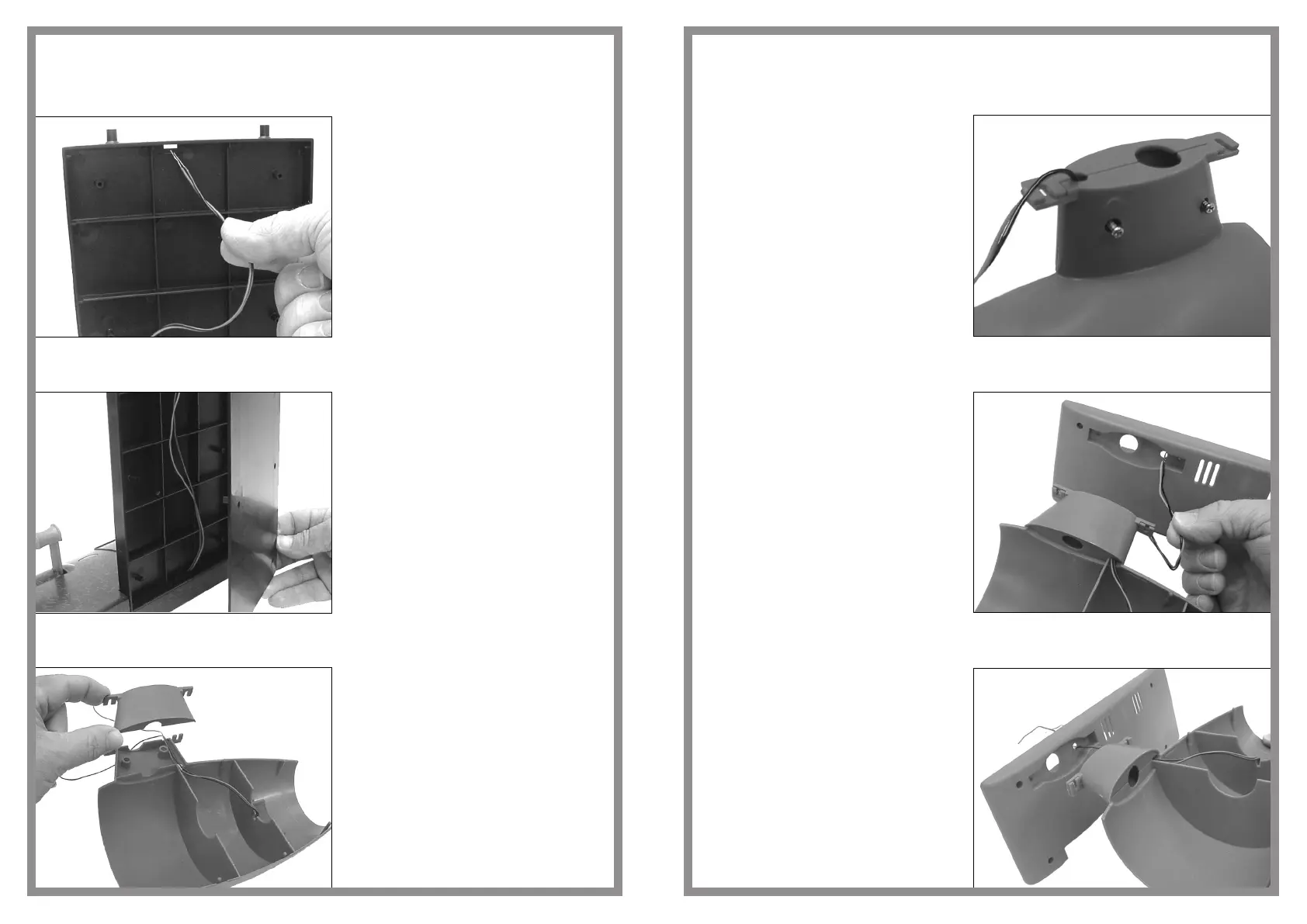
Assembly sequence 28
Assembly sequence 29
Assembly sequence 30
Thread the motor electric cables
through the hole in the top of the
upright support unit
Position and secure the upright
support rear cover onto the upright
support using six screws
Locate the outer pylon cover onto
the inner engine nacelle and pylon
half
Note: Ensure the electric cables
from the nacelle light unit are
threaded through the pylon as
indicated before assembling the
units
jet engine
16
Assembly sequence 31
Assembly sequence 32
Assembly sequence 33
Secure pylon halves using two
screws
Thread the electric cables through
the lower aerofoil as indicated
Locate the pylon and inner engine
nacelle unit into the lower aerofoil
half
17
 Loading...