Do you have a question about the AirSense Stratos Micra 10 and is the answer not in the manual?
Details on certification body, manufacturer, and EU representative.
Information on CE marking, DoP number, EN 54, and product identification.
Information on safety standards and system reacceptance testing.
Legal disclaimer regarding manufacturer liability.
Advises on hazards resulting in injury or loss of life.
Advises on potential equipment damage.
Provides important information and loss of time/effort avoidance.
Indicates components sensitive to static electricity.
Identifies the product as a Class 1 Laser product.
Indicates connections for grounding cable screens.
Guidance for EN 54-20 compliance using PipeCAD software.
Notes on UL certified product approvals and labels.
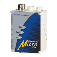
Overview of detector features, specifications, and indicators.
Details on the detector's artificial intelligence for optimum performance.
Free software for detector setup and configuration via RS-232.
Comprehensive list of technical specifications for the detector.
Explains the meaning of the Fire, Fault, and OK indicator lights.
Diagram showing internal parts of the detector.
Identifies terminal blocks, filter, serial port, and address switch.
Detailed view of terminal block connections.
Details connections for power supply and signal interfaces.
Overview of information for installing and configuring the detector.
Step-by-step guide for initial detector installation.
Lists codes and standards for proper installation.
Safety warning about making connections with power off.
Guidelines to reduce electro-static discharge risks.
Guidelines for location, temperature, and humidity.
Requirements for sampling holes, exhaust, and signal cables.
Explains the purpose of the docking station for easy installation.
Identifies cable gland, earth stud, exhaust, sampling ports and mounting holes.
Describes detector use for localized incipient fire detection.
Guidelines for sampling pipe design and EN 54-20 requirements.
Limits one detector per air handling unit.
Ensures sampling pipe is clear of high velocity air.
Illustrates above-ceiling pipework installation with an exposed detector.
Shows detector installation within a ceiling void without exhaust piping.
Lists essential procedures to follow and avoid during installation.
How to fix the docking station and detector.
Details on terminal blocks, wire identification, and RF suppression.
Requirements for the shielded power supply cable and routing.
Step-by-step guide for connecting the power supply.
Specifies cable type and connection to APIC for addressable panels.
Function of the Fire and Fault relays for alarm and fault signaling.
Using relays for conventional and APICs for addressable panels.
Warning about incompatible APIC panel combinations.
How to fit the APIC and connect to the fire panel.
Setting the address using APIC DIP switches.
Each detector needs a unique address from 1 to 127.
Using DIP switch SW1 to set the detector's address.
A table mapping switch settings to detector addresses.
Procedure to slide and fasten the detector body.
Ensuring correct terminal block insertion and cover replacement.
Describes removing the detector as the reverse of installation.
Using PC software for programmable functions.
Software for setting up and configuring detector functions.
Lists available programmable functions for customization.
Direct RS-232 connection or USB adapter.
Diagram of RS-232 cable pin connections.
Shows the physical serial port connection to the PC.
Notes the requirement for a gender changer for UL certified models.
Records faults, alarms, and function changes, stored nonvolatily.
How to view or download event log data via PC.
Overview of information for commissioning the detection system.
Strategy depends on the installation environment.
Emphasizes commissioning must be done by trained personnel.
Visual check of cabling before powering up.
Setting detector address and launching Remote Control software.
Verifying time/date and setting alarm factor.
The detector performs a 15-minute FastLearn for new settings.
Activating demo mode after FastLearn for smoke testing.
Recommended settings for ClassiFire alarms based on environment.
Steps before commissioning, including site cleaning.
Detector operates at reduced sensitivity for 24 hours to learn environment.
Measures smoke transport time and is done at commissioning and annually.
Recommends following local codes and warns against specific test canisters.
Information for troubleshooting the detection system.
Solutions for frequent nuisance alarms.
Solutions when alarms are not triggered by smoke.
Troubleshooting low signal output issues.
Explains normal sensitivity variations and compensation.
Occur when airflow rate exceeds programmed parameters.
Troubleshooting steps for low and high airflow errors.
Provides scheduled and unscheduled maintenance procedures.
Maintenance should be performed at established intervals per regulations.
A typical plan listing 10 scheduled maintenance steps.
Performed every six months to ensure pipe network integrity.
Done at commissioning and annually to verify pipe network performance.
Performed within one year and alternate years thereafter.
Clean exterior with a damp cloth; avoid solvents.
Step-by-step guide for replacing the dust separator filter, including safety notes.
Diagram showing the dust separator cartridge location within the detector.
| Sensor Type | Photoelectric |
|---|---|
| Alarm Sound | 85 dB at 3 meters |
| Interconnectability | No |
| Hush Feature | Yes |
| Low Battery Indicator | Yes |
| End-of-Life Signal | Yes |
| Test Button | Yes |
| Power Source | 10-year sealed lithium battery |