Do you have a question about the Airspan Air4G and is the answer not in the manual?
Specifies minimum safe distances from Air4G antennas for human exposure.
Discusses potential interference from Air4G and mitigation measures.
Provides guidelines for maintaining separation between antennas to prevent interference.
Warns against unauthorized modifications to the device.
Lists general guidelines for installation and usage.
Provides critical safety instructions for installation and operation of Air4G.
Explains warning symbols related to radiation and high voltage hazards.
Details procedures for service and repair, emphasizing qualified personnel.
Covers grounding requirements according to NEC and local safety codes.
Provides general recommendations for lightning protection for the wireless system.
Details FCC compliance, limits for Class A devices, and potential interference.
States GPS compliance with EMC standards and highlights protector requirements.
Outlines the guide's purpose and the installation procedures it covers.
Identifies the target readers for this installation guide.
Explains the informational icons and conventions used throughout the document.
Lists other relevant documents for installation and product information.
Describes the structure and sections of the installation guide.
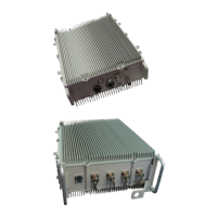
Describes the Air4G base station, its capabilities, and management.
Details the Air4G as a flexible base station for LTE/WiMAX and notes installation requirements.
Presents the overall workflow for installing the Air4G in a diagram.
Recommends using an installation checklist for planning the Air4G setup.
Emphasizes reading warnings, complying with standards, and ascertaining radiation hazards.
Provides specific warnings about hazardous AC and DC voltages during installation.
Lists the necessary tools for installing the Air4G.
Details the parts and kits required for Air4G installation.
Details the steps for mounting the Air4G unit onto a pole.
Guides the installation of a dual slant antenna in a mast mount configuration.
Details the installation process for a quad slant antenna.
Shows adjustable mounting clamp options for dual and quad slant antennas.
Explains the features and adjustment of the variable tilt antenna.
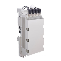
Details the step-by-step process for installing the junction box.
Provides instructions for assembling the environmental Ethernet connector.
Explains the DC power input requirements and connections for the Air4G.
Lists the steps to perform the initial configuration of the Air4G via web interface.
Guides through the General Configuration settings for the base station.
Explains how to configure SNMP settings for network management.
Details the configuration of Management IP settings for the Air4G.
Explains how to set the BS Operational State; no configuration needed.
Lists the required information for reviewing the installation job sheet.
Provides instructions on how to secure fiber-optic cables using Milli-Tie.
Lists the revisions made to the document, including originator and date.
Provides contact details for Airspan customer service and worldwide headquarters.
| Operating Temperature | -40°C to +55°C |
|---|---|
| Mounting | Pole or wall mount |
| Power Supply | 48 VDC |
| Dimensions | 300 mm x 200 mm x 100 mm |
| Interface | Ethernet |