12
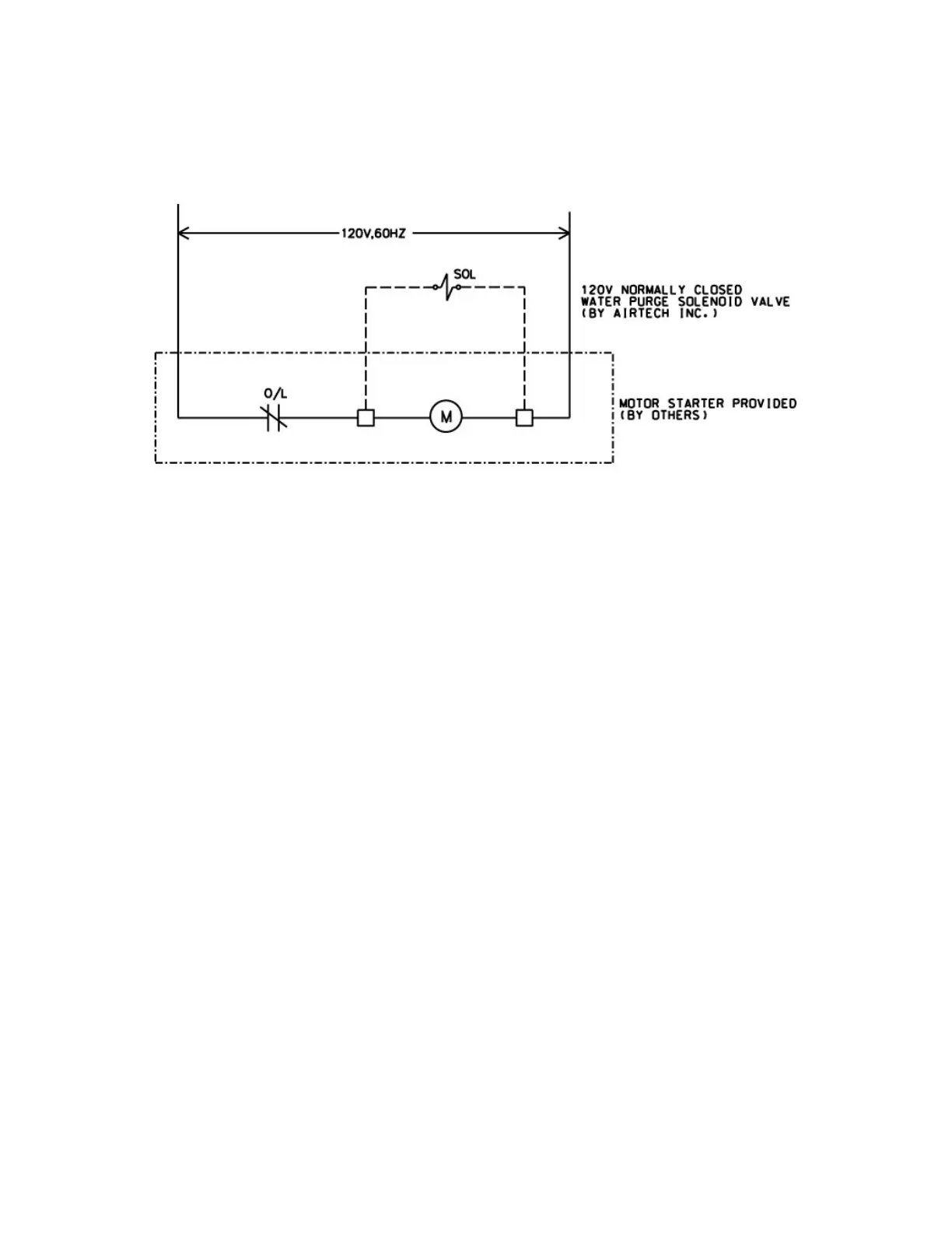
6.6.7 Connect the water supply solenoid valve to the motor control circuit so that
the solenoid valve opens when the motor starter is energized and closed when
the motor starter is de-energized (see Figure 1).
Figure1
6.6.8 Use of a properly sized magnetic motor starter with heater is required to
protect the equipment from electrical failure.
6.7 Once the electrical connections are complete, reattach the junction box cover
and then reattach the 3AL metal cover sheets, ensuring that the wire is properly
routed through the cut out in the side sheet near the bottom of the unit.
6.8 Before making the piping connection to the system, briefly jog the system
(<10 sec) by turning it on and off to check direction of rotation. With a piece of
paper, check the direction of air flow through the system. The paper should be
held against the radiator when the system is operating in the proper direction. If
the paper is blown away from the radiator, then the system is operating in the
incorrect direction and two of the leads must be exchanged in the motor terminal
box.
6.8.1 Ensure the power is de-energized before switching leads inside the
terminal box to change motor direction.
6.9 Fill the system with water in the approximate amount as shown in Section
2.4.
6.9.1 Remove the plastic plug in the top of the 3AL water sump.
6.9.2 Add water to the sump through this connection until the level reaches the
level of the overflow on the back of the unit. Do not use high pressure water to
fill