* SW2-4 must be set to On.
EN: Installation Sheet
Description
DD1012AM(-D)-N is a dual AM motion sensor.
It combines the patented PIR mirror optics technology with the
patented Range Controlled Radar technology.
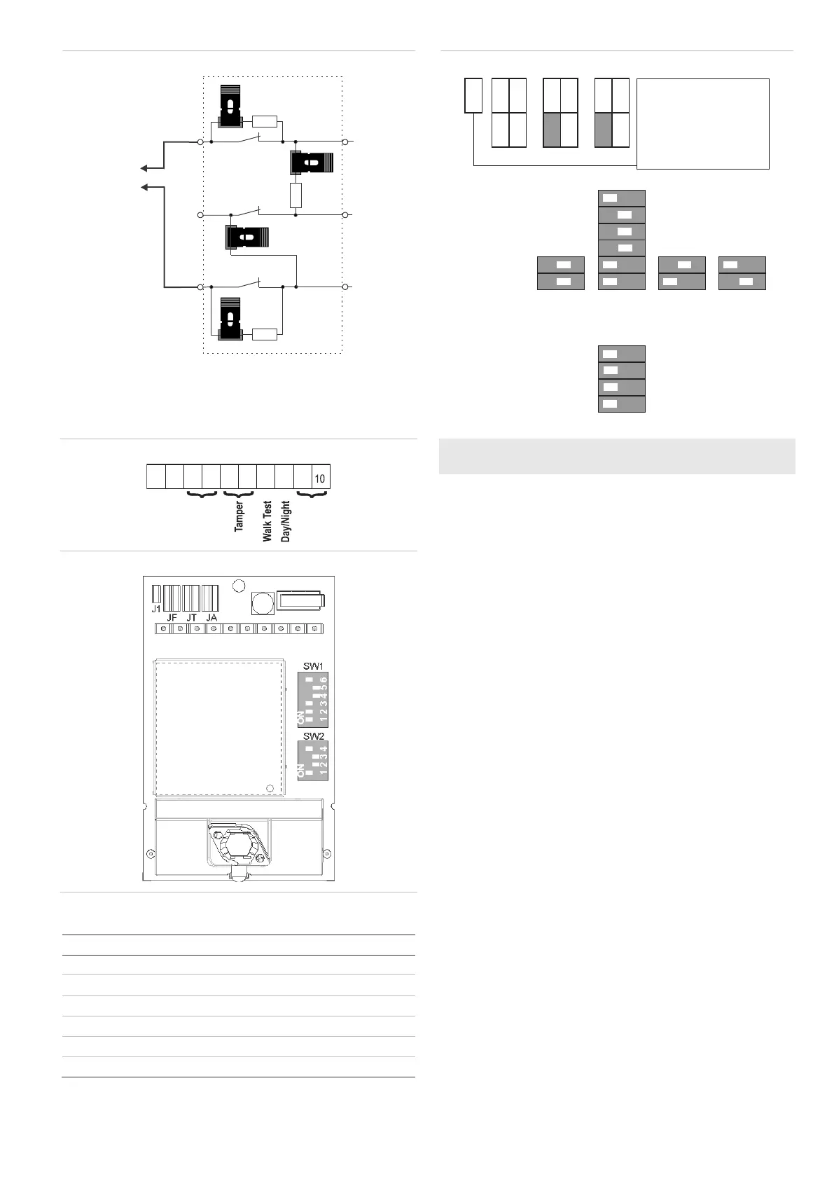
Installation guidelines
See Figure 1.
The detector is intended to be mounted on walls but can also
be mounted on ceilings by using a mounting bracket.
Use the following guidelines to determine the best location to
install the detector.
• Mount the detector so the expected movement of an
intruder is across the detection pattern (see Figure 3).
• Mount the detector at a stable surface. For the allowed
mounting height, see “Specifications” on page 7.
• Do not mount the detector within 0.5 m of metallic objects
or within 1.5 m of fluorescent lights.
• Do not place objects in front of the detector that may
prevent a clear line of sight.
• Place detectors at least 6 m apart, and use the short-
range setting to avoid interference, when mounting
detectors face to face.
The dual technology processing of this detector is very
resistant to false alarm hazards. However, avoid potential
causes of instability, such as:
PIR hazards:
• Direct sunlight on the detector
• Heat sources within the detector field of view
• Strong air draughts onto the detector
• Animals in the field of view
• Obscuring the detector field of view with large objects,
such as furniture
 Loading...