P/N 466-5631-ML • REV C • ISS 15JUL22 7 / 54
Walk testing the detector
There are two ways for switching on the walk test mode.
SW1-6 set to LED on, SW1-5 set to Remote off
In this mode the LED indication is always enabled (constant
walk test mode).
SW1-6 set to LED on, SW1-5 set to Remote on
This setting enables the walk test input (pin 7) and the
day/night input (pin 8). This allows the user to activate LED
indication remotely by setting the detector into the day mode
and activate the walk test.
Green mode
When SW1-5 is set to Remote on, the radar is switched off
during the day mode (with no WT) to reduce current
consumption. The detector is then operating in PIR only mode.
Note: The Day/night line must be connected to the control
panel for this mode to work.
This mode is not compliant with the EN 50131-2-4 standard.
DD1012AM-N only: For first 180 second of the Green mode
operation the detector is switched to high sensitivity PIR mode
to enable additional testing, for example, by using an external
heat source to test against a significant range reduction. After
180 seconds the detector is switched back to the standard
sensitivity.
Alarm memory
When SW1-5 is set to Remote on, alarms that occurred during
the night mode are stored in the detector memory. They are
indicated by flashing red LED when the unit switches to day
mode (walk test disabled). The memory is cleared when the
detector switches back to the night mode.
Note: Set SW1-6 to Off to prevent showing the alarm memory
on the LEDs. See “SW1-6: LEDs” on page 6.
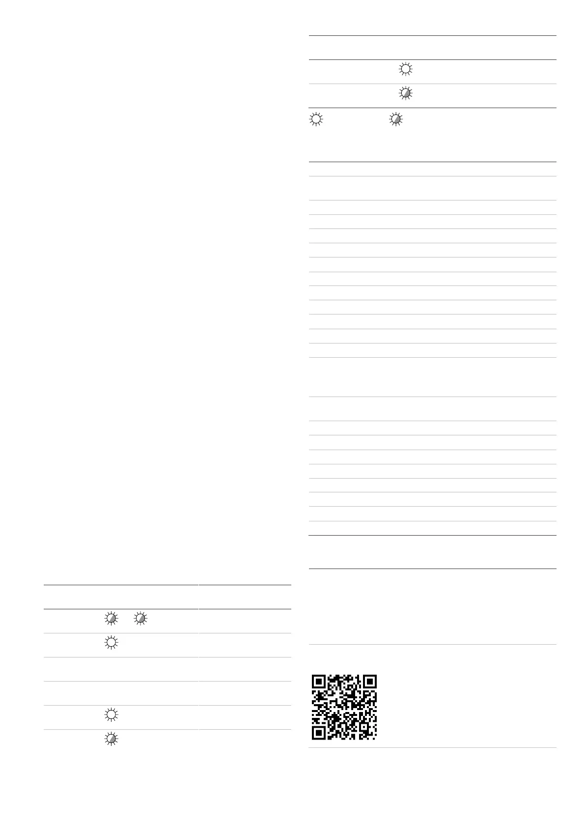
LEDs and outputs
To enable LEDs functionality, set SW1-6 to On, otherwise
LEDs are disabled in any condition. See “SW1-6: LEDs” on
page 6 for more details.
Table 6: LEDs and outputs
PLACED ON THE MARKET BY:
Carrier Fire & Security Americas Corporation Inc.
13995 Pasteur Blvd
Palm Beach Gardens, FL 33418, USA
AUTHORIZED EU REPRESENTATIVE:
Carrier Fire & Security B.V.
Kelvinstraat 7, 6003 DH Weert, Netherlands
THESE PRODUCTS ARE INTENDED FOR SALE
TO AND INSTALLATION BY QUALIFIED
PROFESSIONALS. CARRIER FIRE &
SECURITY CANNOT PROVIDE ANY
ASSURANCE THAT ANY PERSON OR ENTITY
BUYING ITS PRODUCTS, INCLUDING ANY
“AUTHORIZED DEALER” OR “AUTHORIZED
RESELLER”, IS PROPERLY TRAINED OR
EXPERIENCED TO CORRECTLY INSTALL FIRE
AND SECURITY RELATED PRODUCTS.
 Loading...