1
b
a
2
b a c
b
5
SERVICE INFORMATION
21
REPAIR INSTRUCTIONS
Removing the cover
Removing and checking the control unit
Removing the glow pin
Removing the lining
Removing and checking the overheat and ame sensor
Installing the overheat and ame sensor
Dismantling the heat exchanger
Removing the combustion air blower
Removing the combustion chamber
The cover must always be removed from the
AIRTRONIC
for
all repair stages. You may have to wait for the device to cool
down.
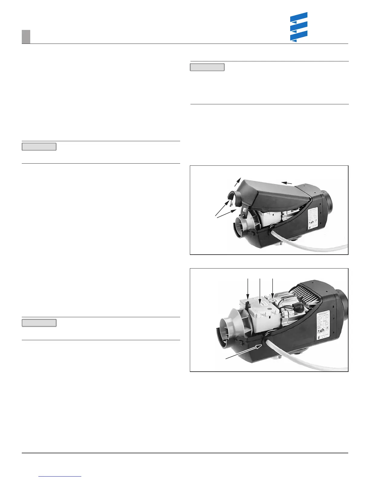
REMOVING THE COVER FROM THE
AIRTRONIC
Unlock both seal plates, lift cover and pull to the front.
The cable harness can exit from the left or right of heater shell.
Cover a
Seal Plates b
REMOVING THE CONTROL UNIT
Remove the
AIRTRONIC
cover.
Unscrew fastening screw, press retaining brackets together, lift out ECU. Unclip
the lines from the holder of the control unit (observe the positions of the lines).
Remove the bushing (lower part) from the outer case. Disconnect the control
unit from the controller. The ECU can now be removed.
When reassembling the ECU, ensure that the lines are
correctly clipped in the holder of the ECU, and that the
connectors are plugged into the ECU (non-interchangeable).
Fastening screw a
Retaining brackets b
ECU c
Bushing d
Remove power from the heater prior to any disassembly
by unplugging main connection or removing main fuse.
If gasket was removed during disassembly, replace it when
reassembling.
Clean all parts before reassembly and check for any signs of
damage, replace where necessary.
Figure 22
Figure 23
PLEASE NOTE!
PLEASE NOTE!
PLEASE NOTE!
REVISION LEVEL A - 09/09/15
 Loading...