90°
b
a
c
a
c
b
b
a
b
a
5
REVISION LEVEL A - 09/09/15
SERVICE INFORMATION
22
RECOMMENDED PERIODIC MAINTENANCE
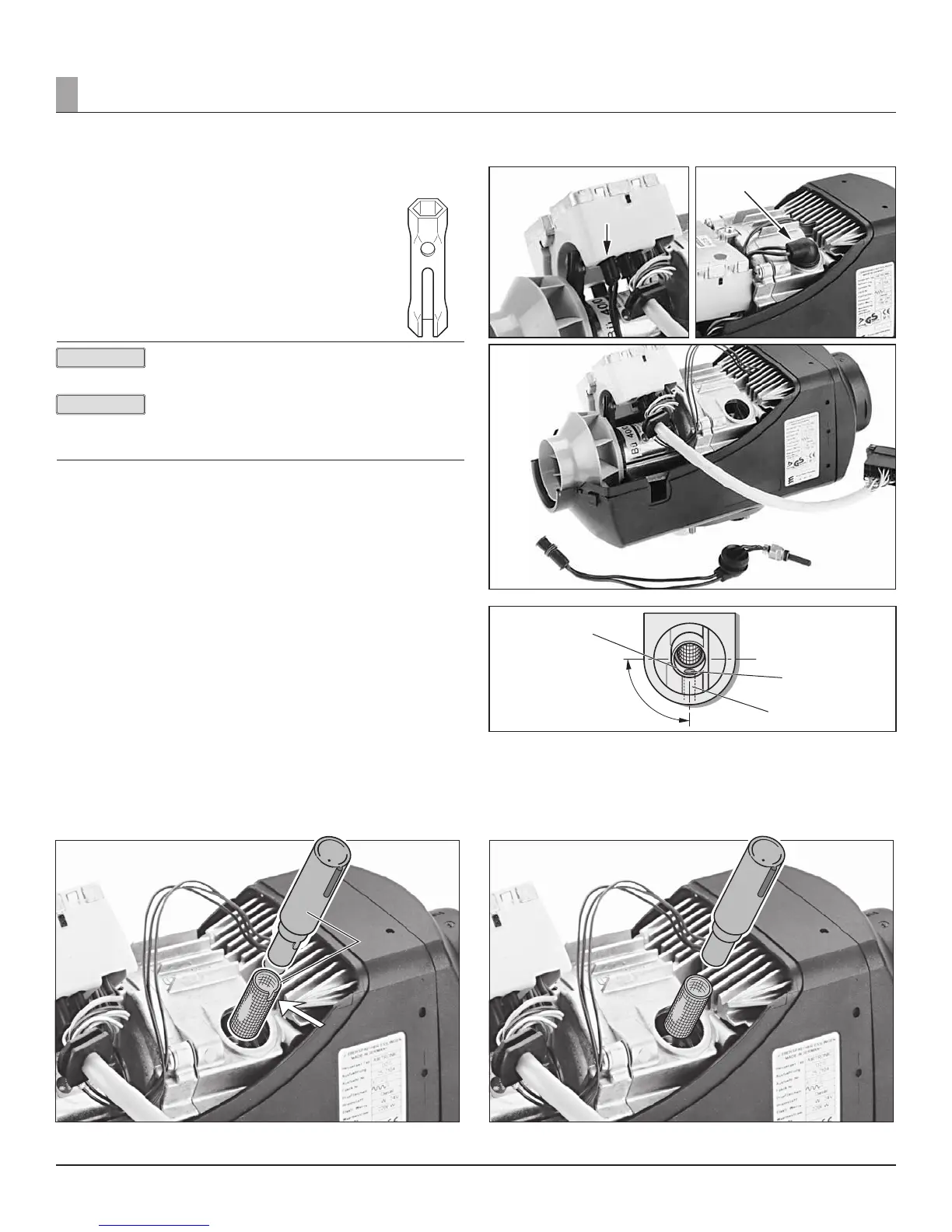
• Remove the AIRTRONIC cover.
• Remove the ECU.
Disconnect the connector of the glow pin cable harness from
the ECU.
Remove the rubber grommet and use the special tool to unscrew
the glow pin.
The special tool is included with the glow pin.*
Tighten torque of the glow pin: 6
+0.5
Nm (50 in•lb)
Please check product catalogue for more information.
When the glow pin has been removed, check the screen of
the support in installed state for any contamination.
The screen must be replaced if the surface is covered with
carbon.
Glow pin a
Connector of glow pin cable harness b
Rubber bushing c
REMOVING THE SCREEN
Pull the screen out of the support with pointed pliers. Blow out the support
with compressed air.
If necessary, carefully pierce with a wire.
The special tool has to be used to install the screen. The special tool is
included with the screen. Push the screen onto the special tool, watching the
position of the recess. The recess must be positioned at right angles (90°) to
the axis of the heater.
Newer screens do not have a recess.
Push the tool with the screen carefully as far as it will go, ensuring that the
bore (ø 2.7 mm) for the glow plug ventilation is free. See illustration 1.
In case of the shorter, new style screen (see image B) the position of the
screen to the vent hole has no reference. Ensure installation tool is completely
seated when installing screen.
Image A
Figure 28
a Special tool
b Position of recess
Figure 24 Figure 25
Figure 26
Figure 27
a Screen
b Bore (Ø 2.7 mm) for glow pin ventilation
c Vent Hole (Can be cleaned with wire)
Allow riveted section to be placed in such a way as to not
block the vent more.
Image B
Figure 29
a Special tool
b Screen
PLEASE NOTE!
PLEASE NOTE!
 Loading...