1
SYSTEM OVERVIEW
The Espar Airtronic D2 heater is designed to lower idling by providing an
alternative in cab heat solution
SYSTEM OPERATION
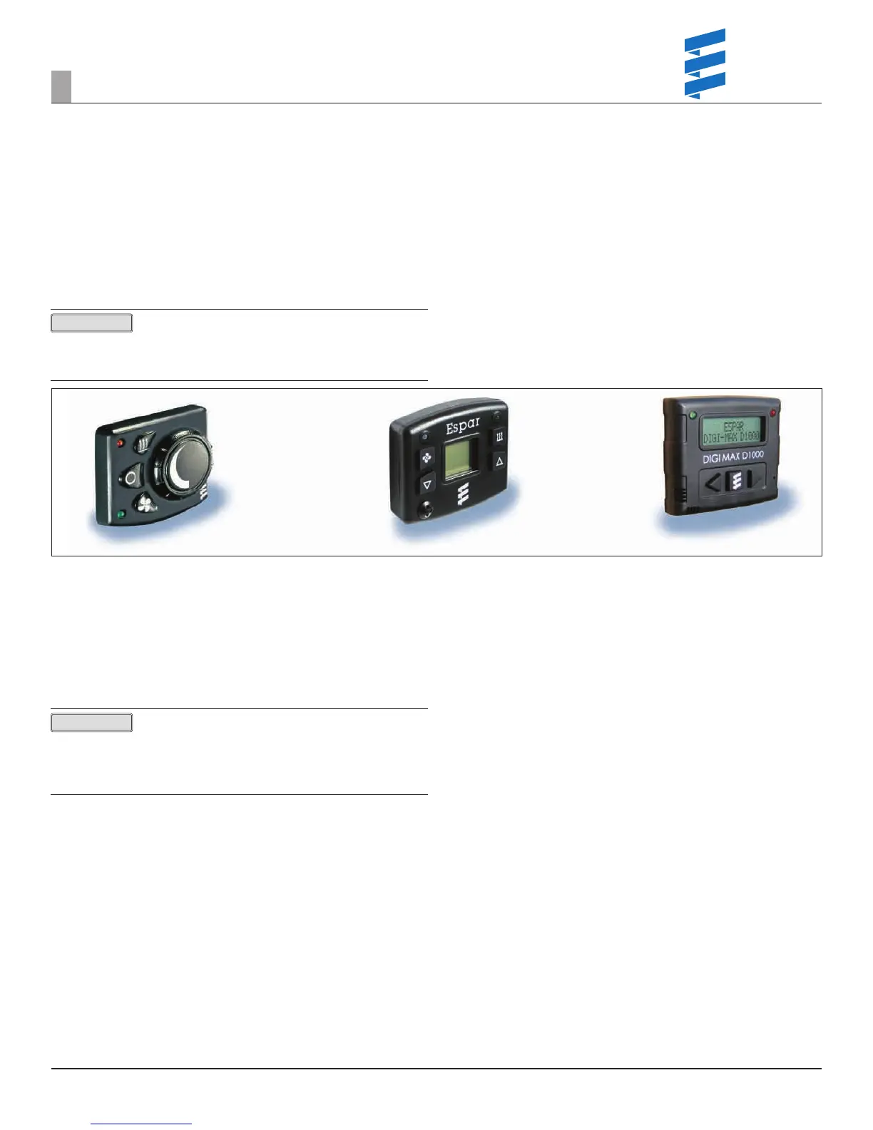
1. The operation turns on the device via either the Mini, Digi or Digi-Max Controller.
a. The Mini-Controller has a simple rheostat design for cab temperature
control (Figure 1).
b. The Digi/Digi-Max Controller are digital devices that controls the cab
temperature and also acts as a diagnostic device (Figure 2 & 3).
If the unit is equipped with a Digi-Controller and the
display is showing H, the interior temp of the unit is too high to allow the
Espar unit to operate. If the display is showing L, the unit will work but the
temp is too cold to show the correct temp on the display.
Figure 1 Figure 2
2. When the heater is rst started the following events take place:
a. The unit runs through a 3 second diagnostic check.
b. The fan and glow pin come on.
c. After 60 seconds the fuel pump starts pumping fuel.
d. If the unit doesn’t re within 2 1/2 minutes:
I. The unit will then stop the fuel pump and pause for 60 seconds.
II. The unit will then attempt a second start.
e. If the unit doesn’t re after the second attempt, a code 52 will be set.
Refer to the fault code section of this document for proper troubleshooting.
Times are approximate, it is more important to understand
there are 2 attempts and the process can takes some time. After the second
failed attempt, the heater fan motor will remain on for up to three minutes
which is normal and part of the logic of the heater. The unit must be allowed
time to run through its cycle. If there is an issue it will trip a code.
3. Inside the unit
a. The fan provides air ow through the combustion chamber and the
ventilation hole.
b. The glow pin heats the atomizer chamber to preheat in preparation for fuel.
c. Fuel rst enters below the ventilation hole.
d. It is then atomized and ignites.
e. The ame burns through the combustion chamber.
f. The ame sensor recognizes a temperature rise and then shuts off the
glow pin.
g. The ECU measures the cab temperature via the return air temperature
sensor in correlation with the set point (Figure 4).
h. Units utilizing the Digi/Digi-Max Controller do not utilize the return air
temp sensor but instead use the remote air temperature sensor on the
“Controller” (Figure 2 & 3 – page 3).
i. The unit switches between boost, high, medium, low and standby.
I. When it rst ignites it is always in boost.
II. Mode is controlled via fuel pump frequency and fan speed.
Figure 3
3
SYSTEM OVERVIEW
PLEASE NOTE!
PLEASE NOTE!
REVISION LEVEL A - 09/09/15
 Loading...