EasyManua.ls Logo

Airwell Itelco-Clima CLS 182 LN - User Manual

Airwell Itelco-Clima CLS 182 LN
83 pages
Print Icon
To Next Page IconTo Next Page
Loading...
English
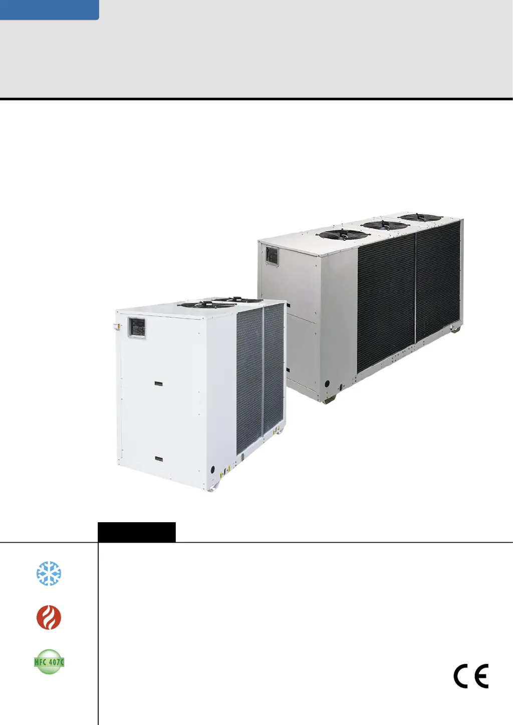
Air cooled water chillers, air cooled condensing units and air-to-water
reverse cycle heat pumps
Installation and maintenance manual
IOM CLSCH-N.1GB
Date : November 2005
Supersedes : None
CLS/CLC/CLH
182 ÷ 602
41
140 kW
46
152 kW
Библиотека СОК

Table of Contents

Questions and Answers

  • S
    Stefanie SaundersAug 17, 2025
    How to fix excessive noise in my Airwell Itelco-Clima CLS 182 LN?
    • M
      Marcus SteeleAug 17, 2025
      Excessive noise in your Airwell Chiller can stem from several sources. Check the following: * Examine the lines for vibration and inspect the clamping brackets, if any, to ensure they are secure. * A whistling sound from the thermostatic expansion valve may indicate the need to refill the system. * Inspect the dehydrating filter. * A noisy compressor could have seized bearings, requiring compressor replacement. * Ensure the compressor’s locknuts are tightened.
  • J
    James BooneAug 21, 2025
    What to do if HP alarm activates and stops my Airwell Itelco-Clima CLS 182 LN Chiller?
    • C
      christina99Aug 21, 2025
      If the HP alarm is activated and your Airwell Chiller stops, consider these possible causes: * Check the operation of the pressure switch and replace it if it's defective. * Ensure the delivery valve is fully open; if faulty, replace it. * The presence of substances with condensable gases in the circuit may require draining the circuit. * If the condenser fan is not working, check its cables and motor; repair or replace as needed.
  • M
    miguel13Aug 25, 2025
    Why does the LP alarm activate and stop my Airwell Chiller?
    • R
      robinsmithAug 25, 2025
      The activation of the LP alarm, which causes your Airwell Chiller to stop, can be due to: * A gas leak. Identify and remove the leak. * Insufficient charge. Refill the system. * Failure of the pressure switch. Replace the pressure switch.
  • K
    Kathleen WagnerAug 27, 2025
    How to troubleshoot an Airwell Itelco-Clima CLS 182 LN Chiller that runs but doesn't cool?
    • M
      Marcus BaileyAug 27, 2025
      If your Airwell Chiller is running but not providing cooling, the issue might be: * Insufficient refrigerant. In this case, you should refill it. * A clogged dehydrating filter. If this is the case, replace it.
  • R
    Rachael HillAug 30, 2025
    What causes a low oil level in the Airwell Itelco-Clima CLS 182 LN Chiller compressor?
    • I
      Ian MccormickAug 30, 2025
      A low oil level in your Airwell Chiller's compressor can be caused by: * One or more gas or oil leaks in the circuit. Identify and remove any leaks. * Mechanical failure of the compressor. Request the intervention of a Service Centre. * Anomaly of the oil heater of the compressor’s base. Check the electric circuit and the resistor of the heater of the motor base, and replace defective components.
  • L
    Lisa HicksSep 3, 2025
    Why is there ice forming on the suction line of my Airwell Itelco-Clima CLS 182 LN Chiller?
    • J
      jasmine68Sep 3, 2025
      Ice formation on the suction line of your Airwell Chiller can be caused by: * Wrong calibration of overheating. Increase overheating. * Check the charge.
  • N
    Nathan CurtisSep 6, 2025
    What causes frosting on the liquid line of my Airwell Chiller?
    • Y
      Yesenia ParkSep 6, 2025
      Frosting on the liquid line of your Airwell Chiller can occur if: * The valve of the liquid line is partially closed. Check that valves are open. * The liquid filter is clogged. Replace the cartridge or the filter.
  • R
    Rachael RussellSep 10, 2025
    Why is the liquid line of my Airwell Itelco-Clima CLS 182 LN Chiller too hot?
    • T
      Tara MontoyaSep 10, 2025
      If the liquid line of your Airwell Chiller is too hot, it may be due to insufficient charge. Identify and remove the cause of the loss of charge and refill.
  • M
    mariawilcoxNov 13, 2025
    What to do if one or both Airwell Itelco-Clima CLS 182 LN Chiller compressors are not working?
    • H
      hursttimothyNov 13, 2025
      If one or both compressors in your Airwell Chiller are not working, there are several potential causes to investigate: * Check the electric circuit for ground dispersions and short circuits, and also check the fuses. Replace fuses if needed. * Inspect for loosened terminals and tighten them. * See if the HP pressure switch has intervened; if so, reset it and the control panel, then restart the appliance after identifying and resolving the cause. * Look for thermal overload in the electric circuit and address the cause. * Verify the wiring of check and safety devices. * Ensure the line voltage is adequate; if too low, address system issues or inform the Energy Distributor if the problem lies with the distribution network. * Check the compressor’s motor for a short-circuit by ...

Summary

Foreword

1.1 Introduction

Overview of Itelco-Clima units and manual content.

1.2 Warranty

Details on warranty conditions and voiding factors.

1.3 Emergency stop; Normal stop

Instructions for emergency and normal unit shutdown procedures.

1.4 An introduction to the manual

Explanation of manual conventions and safety information provided.

Safety

2.1 Foreword

General safety compliance with directives and applicable regulations.

2.2 Definitions

Defines key roles like OWNER and INSTALLER for safety context.

2.3 Access to the Unit

Procedures and requirements for authorized personnel access to the unit.

2.4 General Precautions

Essential safety precautions for operators and installers during unit interaction.

2.5 Precautions Against Residual Risks

Measures to mitigate residual risks related to electrical, mechanical, and control systems.

2.6 Precautions During Maintenance Operations

Safety protocols to follow before and during maintenance tasks.

2.7 Safety Plates

Description and identification of safety labels affixed to the unit.

2.8 Safety Regulations

Covers refrigerant and oil safety data, handling, and disposal guidelines.

Transport, Lifting and Positioning

3.1 Inspection

Guidelines for inspecting the unit upon delivery for any transport damage.

3.2 Lifting

Instructions and safety warnings for the proper lifting of the unit.

3.3 Anchoring

Requirements and considerations for anchoring the unit to its installation base.

3.4 Storage

Precautions for storing the unit safely before its installation.

Installation

4.1 Positioning of the Unit

Criteria and requirements for selecting the optimal unit installation location.

4.2 Installation of Spring Shock Absorbers

Procedure for installing optional shock absorbers to reduce vibration.

4.3 External Hydraulic Circuit

Specifications and components for the external hydraulic circuit.

4.4 Hydraulic Connection

Details on connecting the unit's water inlet and outlet fittings.

4.5 Draining Defrosting Waste Water

Management of defrost water for heat pump units to prevent damage.

4.6 Power Supply

Safety precautions and requirements for the unit's power supply.

4.7 Electrical Connections

Instructions for electrical connections, voltage, and phase balancing.

Start-up

5.1 Preliminary Check

Essential pre-start checks for the unit and its connections.

5.2 Start-up Sequence

Step-by-step procedure for starting the unit and initial operational checks.

5.3 Checking the Operation

Key parameters to verify after start-up for optimal unit performance.

5.4 Delivery to the Customer

Guidance on training the end-user on unit operation and features.

Control

6.1 General Information

Overview of the unit's electronic control system and its functions.

6.2 Control System

Details on temperature regulation, antifreeze, and defrosting functions.

6.3 Display

Explanation of the control panel display, LEDs, and alarm codes.

6.4 Start-up

Procedures for starting the unit for different models (cooling/heat pump).

6.5 Switching the Working Temperature

How to change operating modes and set target temperatures.

6.6 Main Alarms

List of common alarms, their causes, and reset procedures.

General Description

7.1 Introduction

Overview of CLS/CLH units, their purpose, and applications.

7.2 General Specifications

Details on unit construction, materials, and manufacturing process.

7.3 Compressors

Description of hermetic scroll compressors and their protection features.

7.4 Refrigeration Circuits

Explanation of the unit's refrigeration circuits and safety devices.

7.5 Water Heat Exchanger

Specifications and features of the stainless steel plate type water heat exchanger.

7.6 Air Heat Exchanger

Details on the air heat exchanger coils made of copper and aluminum fins.

7.7 Fans

Information on condenser fans, including blades, guards, and motors.

7.8 Electric Power Supply and Control System

Description of the control compartment, keyboard, and display functions.

7.9 Accessories

List of optional accessories and guidance for on-site installation.

Technical Data

8.1 Pressure Drops in the Evaporator

Tables detailing pressure drop values for various evaporator models.

8.2 Technical Data

Comprehensive data for CLS STD, LN, ELN, HPF, HT unit variants.

8.3 Unit Electrical Data

Electrical specifications for CLS/CLC and CLH series units.

8.4 Shock Absorber Positions and Weight Distribution

Diagrams and tables for shock absorber placement and weight distribution.

8.5 Overall Dimensions

Diagrams and tables detailing the overall dimensions of various unit models.

8.6 Service Spaces

Clearance requirements and diagrams for unit installation and service access.

Maintenance

9.1 General Requirements

General guidelines and responsibilities for unit maintenance operations.

9.2 Planned Maintenance

Schedule and description of planned maintenance tasks and inspections.

9.3 Refrigerant Charge

Procedures and warnings for correctly charging the refrigerant circuit.

9.4 Compressor

Information on compressor lubrication, oil, and replacement procedures.

9.5 Condenser

Instructions for cleaning the condenser coils and maintaining efficiency.

9.6 Fans

Checks required for condenser fans, including rotation direction.

9.7 Dehydrating Filter

Procedure for checking and servicing the dehydrating filter and sight glass.

9.8 Sight Glass

Using the sight glass to inspect refrigerant flow and humidity levels.

9.9 Thermostatic Expansion Valve

Procedure for checking and adjusting the thermostatic expansion valve's overheating.

9.10 Evaporator

Guidelines for maintaining the evaporator's water side cleanliness and efficiency.

Spare Parts

11.1 Spare Part List

List of recommended spare parts for unit maintenance.

11.2 Oil for Compressors

Information regarding the type of oil used for compressor lubrication.

11.3 Wiring Diagrams

Location of wiring diagrams and how to obtain them.

Dismantling, Demolition and Scrapping

12.1 Generalities

General procedures, safety, and disposal guidelines for unit dismantling.

Airwell Itelco-Clima CLS 182 LN Specifications

General IconGeneral
BrandAirwell
ModelItelco-Clima CLS 182 LN
CategoryChiller
LanguageEnglish

Related product manuals