12345
Matrix 2019
www.ais-inc.comwww.ais-inc.com
2
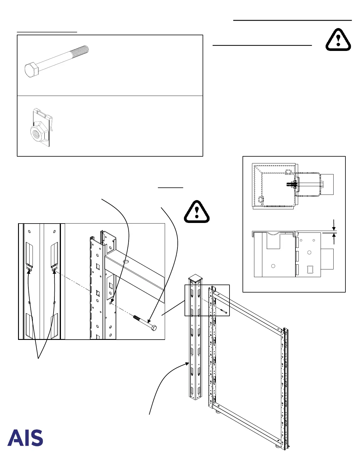
90° Frame Connection
P-MXINSTRUCT01 Rev 07.29.2020
IMPORTANT INSTRUCTIONS:
• Place first bolt at top of frame, below first
electrical chase hole. This hole is round
and will align frames vertically. All other
bolt locations are slots.
• Thread all bolts loosely, making sure
bolts are properly threaded to prevent
cross-stripping. Tighten top bolt first,
then tighten all remaining bolts to approx.
100 inch lbs torque, or using a 12 volt
drill on medium torque.
Required hardware:
¼-20 x 2 ¼” Hex Bolt
#RP-M2BOLT1
Use 7/16” magnetic hex drive
82H Frame = 5 bolts
50-66H Frame = 4 bolts
34-42H Frame= 3 bolts
¼-20 Tinnerman Nut
#RS-HNC33892
(Factory installed, on one side of
frame. Installers may be required to
remove from frames if connecting to
2-way, 3-way or 4-way connector)
1/8”
Top View
Side View
90° Connector
(2-way, 3-way or 4-way)
¼-20 Tinnerman Nut
May have moved during shipping.
To re-center, briefly insert
#2 philips screw driver through
connector hole into the
tinnerman nut.
¼-20 x 2 ¼” Hex Bolt
First bolt must be installed at
top of frame to ensure proper
vertical alignment
If necessary, remove
¼-20 Tinnerman Nut
located on frames prior
to bolting on connector
 Loading...