EasyManua.ls Logo

Aiwa CSD-TD901 User Manual

Aiwa CSD-TD901
42 pages
To Next Page IconTo Next Page
Page #1 background imageLoading...
Page #1 background image
SERVICE MANUAL
DA
T
A
CD STEREO RADIO
CASSETTE RECORDER
S/M Code No. 09-027-361-3R1
REVISION
BASIC TAPE MECHANISM:TN-21ZVC-2000
BASIC CD MECHANISM :KSM-213 RDM
• This Service Manual is the “Revision Publishing” and replaces “Simple Manual”
(S/M Code No. 09-027-361-3T1).
LH(ST)
CSD-TD9
CSD-TD901
U(ST),UC(ST)
CSD-TD902
U(S),UC(S)
Ver. 1.0
w
w
w
.
x
i
a
o
y
u
1
6
3
.
c
o
m
Q
Q
3
7
6
3
1
5
1
5
0
9
9
2
8
9
4
2
9
8
T
E
L
1
3
9
4
2
2
9
6
5
1
3
9
9
2
8
9
4
2
9
8
0
5
1
5
1
3
6
7
3
Q
Q
TEL 13942296513 QQ 376315150 892498299
http://www.xiaoyu163.com
Question and Answer IconNeed help?

Do you have a question about the Aiwa CSD-TD901 and is the answer not in the manual?

Aiwa CSD-TD901 Specifications

General IconGeneral
BrandAiwa
ModelCSD-TD901
CategoryStereo System
LanguageEnglish

Summary

Service Manual Overview

Model Identification and Key Mechanisms

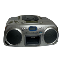
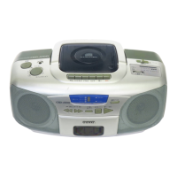
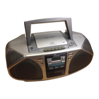
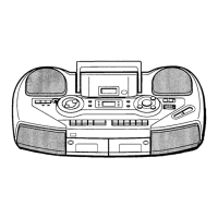
Identifies models CSD-TD9, TD901, TD902 and their basic tape/CD mechanisms.

Specifications

Tuner, Deck, CD Player, and General Specs

Details technical specifications for unit sections and overall unit characteristics.

Laser Safety Precautions

Eye Protection During Servicing

Crucial safety instructions to protect eyes from laser radiation during service procedures.

Optical Block Replacement Precautions

Electrostatic Discharge Prevention

Advises on preventing electrostatic discharge from damaging the laser diode during optical block replacement.

ELECTRICAL PARTS LIST -1/9

BLOCK DIAGRAM -1/2

Cassette Section Block Diagram

Illustrates the functional blocks and interconnections for the cassette section.

BLOCK DIAGRAM -2/2

Tuner and CD/Control Section Block Diagrams

Illustrates functional blocks for tuner and CD/control sections.

SCHEMATIC DIAGRAM -1/4 (MAIN -1/3) <AMP>

Amplifier Section Schematic

Detailed circuit schematic for the amplifier section of the unit.

SCHEMATIC DIAGRAM -2/4 (MAIN -2/3) <CD>

CD Section Schematic

Detailed circuit schematic for the CD player section of the unit.

SCHEMATIC DIAGRAM -3/4 (MAIN -3/3) <TUNER>

Tuner Section Schematic

Detailed circuit schematic for the tuner section of the unit.

WIRING -1/3 (MAIN)

WIRING -2/3 (CASETTE)

SCHEMATIC DIAGRAM-4/4 (CONTROL/RECTIFIER/BATT-1/BATT-2)

WIRING-3/3 (CONTROL/RECTIFIER/BATT-1/BATT-2)

VOLTAGE CHART -1/2

ELECTRICAL ADJUSTMENT -1/1

CD TEST MODE -1/1

IC BLOCK DIAGRAM -1/2

IC BLOCK DIAGRAM -2/2

IC DESCRIPTION -1/1 (IC,TC94A23F) -1/3

MECHANICAL PARTS LIST -1/2

Related product manuals