Do you have a question about the Aiwa GFHN CSD-FD83 and is the answer not in the manual?
Details FM/AM/LW frequency ranges and antenna types.
Covers tape track format, frequency, recording, erasing, and heads.
Details disc type and scanning method.
Includes speaker types and output power details.
Outlines power sources, consumption, and voltage.
Lists the physical size and weight of the unit.
Important safety warnings regarding laser exposure during servicing.
Specific steps and precautions for handling the optical block.
Lists primary electrical components like ICs, transistors, and diodes.
Lists parts for Main and CD circuit boards.
Provides visual diagrams of transistor pinouts.
Schematic diagram for the CD motor.
| Brand | Aiwa |
|---|---|
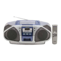
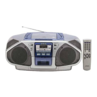
| Model | CSD-FD83 |
| Recorder Type | Stereo |
| Signal-to-Noise Ratio | 50 dB |
| Power Source | AC, Batteries |
| Frequency Response | 40 Hz - 14 kHz |