This document is a service manual for the AIWA HS-PS201 stereo cassette player, covering models Y, YJ, and YU. It provides essential information for servicing the device, including specifications, parts lists, wiring diagrams, schematic diagrams, and adjustment procedures.
Function Description
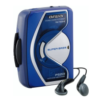
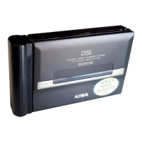
The AIWA HS-PS201 is a portable stereo cassette player designed for audio playback from compact cassette tapes. It features a basic tape mechanism (4ZM-2 P12NC) and includes a "SUPER BASS" function to enhance low-frequency audio output. The device is intended for personal listening, typically through headphones.
Important Technical Specifications
- Maximum Output:
- 15 mW + 15 mW (EIAJ 32 ohms) for YU, YJ models.
- 4 mW + 4 mW (EIAJ 16 ohms) for Y model.
- Power Source: DC 3V, supplied by two size AA (R6) batteries.
- Maximum Dimensions: 116.6 (W) x 92.0 (H) x 35.3 (D) mm (approximately 4 5/8 x 3 5/8 x 1 7/16 inches).
- Weight: Approximately 108.5 g (3.8 oz), excluding batteries.
- Basic Tape Mechanism: 4ZM-2 P12NC.
- Integrated Circuit (IC): TA2145F.
- Diode: 1SS184 (chip diode).
- Capacitors: A variety of capacitors are used, including ceramic (e.g., 1800P-50KB, 8200P-50KB, 1500P-50KB, 0.1-25ZF, 1-16ZF, 0.22-16ZF), electrolytic (e.g., 22-6.3M SRA, 220-4.7L SR, 10-16, 1UF 50V TAPG).
- Resistors: Includes chip resistors (e.g., 180-1/10W F) and a semi-fixed resistor (1K).
- Variable Resistor (VR): RTRY 20KBX1 for volume control.
- Switches: Features a leaf switch (LSA1120JAU) and a slide switch (SS-350-B12W-C-L) for the SUPER BASS function.
- Motor: BCY3B-13.
- Head: AP 4211TA.
- Jack: 3.5 ST BLK (for headphones).
Usage Features
The device is a straightforward cassette player. Key user-facing features include:
- Stereo Cassette Playback: Standard functionality for playing audio cassettes in stereo.
- Volume Control: Adjustable via a rotary variable resistor (VR1).
- SUPER BASS Function: A switch (SW401) allows the user to turn the SUPER BASS enhancement on or off, providing an option for boosted bass frequencies.
- Headphone Output: A 3.5mm stereo jack (J1) is provided for connecting headphones.
- Battery Operation: Powered by two AA batteries, making it portable.
- Belt Clip: Included as an accessory for convenient carrying.
Maintenance Features
The service manual provides detailed instructions and diagrams crucial for maintenance and repair:
- Electrical Main Parts List: Comprehensive list of ICs, diodes, capacitors, resistors, jacks, and switches used in the main and front circuit boards, including part numbers and descriptions.
- Mechanical Parts List: Detailed list of mechanical components such as knobs, panels, lids, plates, springs, frames, contacts, screws, and the tape head, with part numbers and descriptions.
- Wiring Diagram: Illustrates the electrical connections between the main circuit board, front circuit board, motor, battery, and external components like headphones and the play head.
- Schematic Diagram: Provides a detailed circuit diagram of the main and front boards, showing component interconnections and signal paths, including the IC (TA2145F) and its associated circuitry for pre-amplification, power amplification, and motor control.
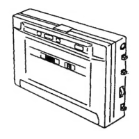
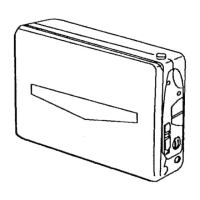
- Mechanical Exploded Views: Diagrams showing the disassembled views of both the overall device and the tape mechanism, aiding in component identification and reassembly.
- Adjustment Procedures:
- Tape Speed Adjustment: Involves using a TTA-100 test tape and adjusting the SFR51 component to achieve a 3000Hz ±10Hz frequency output at the PHONES JACK (J1).
- Head Azimuth Adjustment: Requires a TTA-300 test tape and adjusting the head azimuth screw to maximize output and ensure correct phase at the PHONES JACK (J1).
- Color Name Table: A reference table for various color codes used in the parts list (e.g., Black, Cream, Orange, Blue, Silver, Yellow, Metallic Blue, etc.).
- Chip Resistor Part Coding: Explains the coding system for chip resistors, including wattage, type, tolerance, symbol, dimensions, and resistor code.
These features enable technicians to diagnose issues, replace faulty components, and calibrate the device for optimal performance.