Do you have a question about the Aiwa NSX-DR4 and is the answer not in the manual?
Details FM, MW, LW tuner specs and amplifier power, distortion, inputs/outputs.
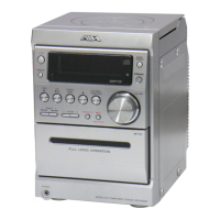
Covers CD player specs (laser, D-A) and cassette deck specs (format, response, heads).
Details speaker system parameters and general unit requirements, consumption, dimensions.
Critical safety warnings for eye protection during laser servicing, including international advisories.
Precautions regarding static discharge when replacing the optical pickup block.
Procedure for safely discharging power supply capacitors before starting repairs.
Essential checks before replacing the microcomputer, focusing on the HOLD terminal and reset.
Lists of integrated circuits, transistors, and diodes with part numbers and descriptions.
Detailed listing of capacitors and other components on the main circuit board.
Explanation of chip resistor coding and visual representations of transistors.
Diagram showing grid assignment for the FL display component (10-BT-224GNK).
Wiring diagram for the main circuit board, detailing connections.
Wiring diagram for the front circuit board, covering controls and display.
Wiring diagram for the tape mechanism, showing Deck 1 and Deck 2 connections.
Detailed schematics for the amplifier (p.13) and tuner (p.14) sections.
Detailed schematics for the front (p.16) and PT (p.17) circuit boards.
Detailed schematic diagram for the 3CD circuit board.
Block diagrams showing internal structure and pin functions of key ICs.
Detailed pinout and functional descriptions for specific ICs like LC78622NE.
Procedures for tuning, VT, tracking, and IF adjustments for tuner sections.
Procedures for tape speed, azimuth, and frequency response adjustments for decks.
Procedure for adjusting the u-CON OSC in the front section.
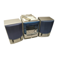
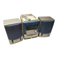
Exploded view of the main unit's mechanical components.
Comprehensive lists of mechanical parts and tape mechanism parts.
Table mapping basic color symbols to their corresponding color names.
Step-by-step instructions for disassembling speaker units.
Specific methods for removing the speaker's front panel using tools.
List of parts for the SX-NBL11 speaker system.
List of included accessories and package contents.
Procedure to adjust the rotating phase of the gear and main cam for correct operation.
Oscilloscope waveforms for key IC test points to verify signal integrity.
Diagram illustrating interconnections between major system sections and ICs.
Instructions for activating, cancelling, and using functions within the CD test mode.
Detailed pinout and functional descriptions for specific ICs like LC78622NE.
Glossary of terms for electrical components and their functions.
Glossary of terms for mechanical parts and their functions.
| CD Player | Yes |
|---|---|
| Remote Control | Yes |
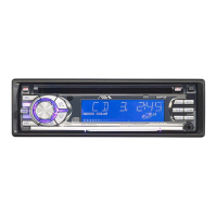
| Display | LCD |
| Equalizer | Yes |
| Radio Tuner | AM/FM |