Do you have a question about the Aiwa NSX-BL14 and is the answer not in the manual?
Detailed technical specifications for FM reception.
Specifications for AM and Medium Wave reception.
Power output and distortion specifications.
Speaker unit impedance and sensitivity details.
Specifications for the cassette tape mechanism.
Safety notices regarding laser exposure during servicing.
Precautions for replacing the optical pickup block.
Steps to safely discharge power supply capacitors before repair.
Checking HOLD terminal status and microcomputer judgement.
Resetting procedures and confirming soldering state.
Block diagram for the M62495AFP IC.
Block diagram for the LA1844L-A IC.
Block diagram for the LC72131D IC.
Schematics for the main amplifier circuits.
Schematics for the tuner and radio reception circuits.
Wiring layouts for the main board.
Schematics for the power transformer circuits.
Wiring layouts for the power transformer section.
Wiring for the cassette tape deck mechanism.
Detailed pin functions for the M38B57MCH-E236FP IC.
Guides for tuning reception adjustments.
Procedures for tape deck performance tuning.
Adjustment for u-CON OSC.
Visual breakdown of mechanical parts.
Lists of mechanical components.
Instructions and parts for speaker units.
| Brand | Aiwa |
|---|---|
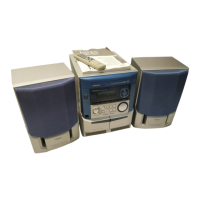
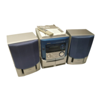
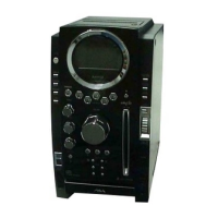
| Model | NSX-BL14 |
| Category | Car Receiver |
| Language | English |