EasyManua.ls Logo

Aiwa CDC-R504MP User Manual

Aiwa CDC-R504MP
50 pages
To Next Page IconTo Next Page
Page #1 background imageLoading...
Page #1 background image
1
Ver 1.0 2004. 01
Model Name Using Similar Mechanism CDX-R3300/R3300T
CD Drive Mechanism Type MG-611MA-186//Q
Optical Pick-up Name KSS1000E
SERVICE MANUAL
US Model
Canadian Model
CDC-X504MP
AEP Model
UK Model
CDC-R504MP/X504MP
CDC-R504MP/X504MP
AUDIO POWER SPECIFICATIONS (US MODEL)
POWER OUTPUT AND TOTAL HARMONIC DISTORTION
23.2 watts per channel minimum continuous average power into
4 ohms, 4 channels driven from 20 Hz to 20 kHz with no more
than 5% total harmonic distortion.
Tuner section
FM
Tuning range US, Canadian Model:
87.5 – 107.9 MHz
AEP, UK Model:
87.5 – 108 MHz
Antenna terminal External antenna connector
Intermediate frequency 10.7 MHz/450 kHz
Usable sensitivity 9 dBf
Selectivity 75 dB at 400 kHz
Signal-to-noise ratio 67 dB (stereo),
69 dB (mono)
Harmonic distortion at 1 kHz
0.5% (stereo),
0.3% (mono)
Separation 35 dB at 1 kHz
Frequency response 30 – 15,000 Hz
AM (US, Canadian Model)
Tuning range 530 – 1,710 kHz
Antenna terminal External antenna connector
Intermediate frequency 10.7 MHz/450 kHz
Sensitivity 30 µV
MW/LW (AEP, UK Model)
Tuning range MW: 531 – 1,602 kHz
LW: 153 – 279 kHz
Antenna terminal External antenna connector
Intermediate frequency 10.7 MHz/450 kHz
Sensitivity MW: 30 µV
LW: 40 µV
CD player section
Signal-to-noise ratio 120 dB
Frequency response 10 – 20,000 Hz
Wow and flutter Below measurable limit
SPECIFICATIONS
Power amplifier section
Outputs Speaker outputs
(sure seal connectors)
Speaker impedance 4 – 8 ohms
Maximum power output 52 W × 4 (at 4 ohms)
General
Outputs Audio outputs terminal (rear/sub switchable)
Power antenna relay control terminal
Power amplifier control terminal
Inputs Telephone ATT control terminal (AEP, UK Model)
Antenna input terminal
Tone controls Low: ±10 dB at 60 Hz (HIP-HOP)
Mid: ±10 dB at 1 kHz (HIP-HOP)
High: ±10 dB at 10 kHz (HIP-HOP)
Power requirements 12 V DC car battery (negative ground)
Dimensions Approx. 178 × 50 × 176 mm
(7 1/8 × 2 × 7 in.) (w/h/d)
Mounting dimensions Approx. 182 × 53 × 161 mm
(7 1/4 × 2 1/8 × 6 3/8 in.) (w/h/d)
Mass Approx. 1.2 kg (2 lb. 10 oz.)
Supplied accessories Parts for installation and connections (1 set)
Front panel case (1)
Card remote control RM-Z304
Design and specifications are subject to change without
notice.
• The tuner and CD sections have no adjustments.
Sony Corporation
e Vehicle Company
Published by Sony Engineering Corporation
9-877-518-01
2004A04-1
© 2004. 01
Photo: CDC-X504MP
FM/AM COMPACT DISC PLAYER
US, Canadian model
FM/MW/LW COMPACT DISC PLAYER
AEP, UK model
Question and Answer IconNeed help?

Do you have a question about the Aiwa CDC-R504MP and is the answer not in the manual?

Aiwa CDC-R504MP Specifications

General IconGeneral
BrandAiwa
ModelCDC-R504MP
CategoryCar Receiver
LanguageEnglish

Summary

Product Specifications

Audio Power Output

Detailed power output and total harmonic distortion specifications.

Tuner Section Specifications

FM and AM tuning ranges, sensitivity, selectivity, and frequency response.

CD Player Section Specifications

Signal-to-noise ratio and frequency response for CD playback.

Power Amplifier and General Specifications

Amplifier outputs, speaker impedance, power requirements, and general unit dimensions.

Service Notes and Safety Precautions

Handling the Optical Pick-up Block

Guidelines for safely handling the optical pick-up block and its components.

Laser Diode Emission Check

Procedure and safety precautions for checking the laser diode output.

Chip Component Handling

Precautions for replacing chip components and handling tantalum capacitors.

Test Disc Usage

Recommended test discs for checking CD-R and CD-ROM playback capability.

Safety-Related Component Warning

Warning about critical components for safe operation and replacement instructions.

CD Media Compatibility and Soldering Practices

Notes on CD-R and CD-RW Playback

Information on compatible CD formats, playback limitations, and MP3 file support.

Unleaded Solder Guidelines

Characteristics and handling instructions for unleaded solder used in assembly.

Extension Cable for Servicing

Connection method for the main and servo boards using an extension cable for service.

General Operation and Adjustments

Location of Controls

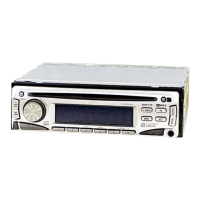
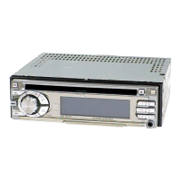
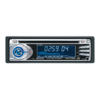
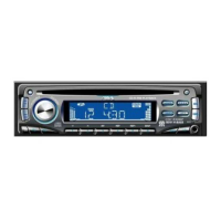
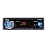
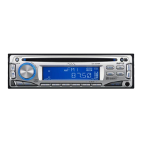
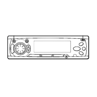
Identification and function of the unit's front panel controls.

Basic Operation and Clock Setting

Procedures for turning the unit on/off, setting the clock, and display functions.

Audio Adjustments

Adjusting volume, sound attenuation, sound stage (DSSA), and sound characteristics.

Bass Reinforcement and Equalizer Settings

Using H-BASS for bass boost and selecting/adjusting equalizer curves.

Connections (US, Canadian Model)

US/Canadian Model Connection Diagram

Visual representation of wiring and component connections for US/Canadian models.

US/Canadian Power and Speaker Notes

Important notes regarding power supply, antenna, and speaker connections.

Connections (AEP, UK Model)

AEP/UK Model Connection Diagram

Visual representation of wiring and component connections for AEP/UK models.

AEP/UK Power and Speaker Notes

Important notes regarding power supply, antenna, and speaker connections.

Disassembly Procedure

Disassembly Sequence Overview

Step-by-step guide outlining the order for disassembling the unit.

Disassembly - Front Panel and CD Mechanism

Sub Panel Assembly Removal

Instructions for removing the front sub panel assembly.

CD Mechanism Block Removal

Instructions for removing the CD mechanism block.

Disassembly - Main Board and Chassis

Main Board Removal

Instructions for removing the main circuit board.

Chassis (T) Sub Assembly Removal

Instructions for removing the chassis (T) sub assembly.

Disassembly - Mechanical Assemblies

Roller Arm Assembly Removal

Instructions for removing the roller arm assembly and related parts.

Chassis (OP) Assembly Removal

Instructions for removing the chassis (OP) assembly and related parts.

Disassembly - Optical Pick-up and Motor Assemblies

Optical Pick-up Removal

Instructions for removing the optical pick-up unit.

SL Motor Assembly (M902) Removal

Instructions for removing the SL motor assembly.

Disassembly - Loading Motor and Servo Board

LE Motor Assembly (M903) Removal

Instructions for removing the LE motor assembly.

Servo Board Removal

Instructions for removing the servo board.

IC Pin Descriptions (Digital Servo/Signal Processor)

IC3 CXD3059AR Pin Assignments

Detailed pin assignments and descriptions for the CXD3059AR IC.

IC Pin Descriptions (System Control)

IC501 MN101E01KSH Pin Assignments

Detailed pin assignments and descriptions for the MN101E01KSH IC.

CD Section Block Diagram

CD Signal Path Diagram

Overall block diagram illustrating the CD playback signal flow and components.

Main Section Block Diagram

Main Unit Signal Flow Diagram

Block diagram showing the main unit's internal signal paths and functional blocks.

Display Section Block Diagram and Board Locations

Display Interface Block Diagram

Block diagram illustrating the display and control interface functions.

Circuit Boards Location Diagram

Diagram showing the physical placement of the main circuit boards within the unit.

Diagram Notes and Waveforms

Notes for Printed Wiring Boards and Schematics

Common notes and conventions used in the schematic and PWB diagrams.

Signal Waveform Measurements

Representative waveforms measured at various points in the servo and main boards.

Printed Wiring Boards - CD Mechanism Section

Servo Board Printed Wiring Layout

Layout of the printed wiring board for the servo section, showing component placement.

Schematic Diagrams - CD Mechanism Section

CD Mechanism Schematic (Part 1)

First part of the schematic diagram for the CD mechanism circuitry.

Schematic Diagrams - CD Mechanism Section

CD Mechanism Schematic (Part 2)

Second part of the schematic diagram for the CD mechanism circuitry.

Schematic Diagrams - Main Section

Main Section Schematic (Part 1)

First part of the schematic diagram for the main unit's circuitry.

Schematic Diagrams - Main Section

Main Section Schematic (Part 2)

Second part of the schematic diagram for the main unit's circuitry.

Printed Wiring Board - Main Section

Main Board Printed Wiring Layout

Layout of the printed wiring board for the main unit, showing component placement.

Printed Wiring Boards - Display Section

Key Board Printed Wiring Layout

Layout of the printed wiring board for the key input section.

Schematic Diagram - Display Section

Display Interface Schematic Diagram

Schematic diagram illustrating the display interface and control logic.

IC Block Diagrams (Servo Board)

IC1 LA6560-TE-L-E Block Diagram

Functional block diagram for the LA6560-TE-L-E servo driver IC.

IC Block Diagrams (Servo & Main Boards)

IC7 R1114N151D-TR-FA (Servo Board) Block Diagram

Functional block diagram for the R1114N151D-TR-FA IC.

IC51 TDA7333-013TR (Main Board) Block Diagram

Functional block diagram for the TDA7333-013TR audio processing IC.

IC Block Diagrams (Main Board)

IC401 BD3809FS (Main Board) Block Diagram

Functional block diagram for the BD3809FS audio control IC.

IC Block Diagrams (Main Board)

IC750 TDA8588BJ/N2 (Main Board) Block Diagram

Functional block diagram for the TDA8588BJ/N2 power amplifier IC.

Exploded Views - Main Section

Main Section Assembly Breakdown

Exploded view showing the assembly of the main unit and its core components.

Exploded Views - Front Panel Section

Front Panel Assembly Breakdown

Exploded view illustrating the front panel components and their assembly.

Exploded Views - CD Mechanism Section (1)

CD Mechanism Section (1) Assembly Breakdown

Exploded view of the CD mechanism, showing chassis and initial components.

Exploded Views - CD Mechanism Section (2)

CD Mechanism Section (2) Assembly Breakdown

Exploded view of the CD mechanism, detailing motor and lever assemblies.

Exploded Views - CD Mechanism Section (3)

CD Mechanism Section (3) Assembly Breakdown

Exploded view showing parts of the CD mechanism, including motor and lever components.

Exploded Views - CD Mechanism Section (4)

CD Mechanism Section (4) Assembly Breakdown

Exploded view detailing the CD mechanism gears, levers, and chassis parts.

Electrical Parts List - Key Components

Auxiliary Boards and Key Components

List of parts for auxiliary boards, key components, capacitors, diodes, and resistors.

Electrical Parts List - Resistors, Switches, and Boards

Resistors, Switches, and Vibrators

Part numbers for resistors, switches, and vibrator components.

Servo Board Components

List of capacitors, connectors, and ICs for the servo board.

Electrical Parts List - Main Board Components

Main Board Capacitors and Diodes

Part numbers for capacitors and diodes used on the main board.

Electrical Parts List - Main Board Components

Main Board Diodes, ICs, and Jacks

Part numbers for diodes, ICs, and jacks on the main board.

Main Board Resistors, Transistors, and Coils

Part numbers for resistors, transistors, and coils on the main board.

Electrical Parts List - Main Board Resistors

Main Board Resistors (Continued)

Continuation of the parts list for resistors on the main board.

Electrical Parts List - Sensor and Servo Board Components

Main Board Resistors (Continued)

Further listing of main board resistors.

Sensor and Servo Board Components

Part numbers for sensor board switches, vibrators, and servo board components.

Electrical Parts List - Servo Resistors and Accessories

Servo Board Resistors and Switches

Part numbers for servo board resistors and switches.

Miscellaneous Parts and Accessories

Listing of miscellaneous items and accessories, including remote control.

Electrical Parts List - Accessories and Installation Parts

Accessories and Installation Parts

Detailed list of accessories and parts for unit installation.

Revision History

Revision Details

Record of revisions made to the service manual.

Related product manuals