Do you have a question about the Aiwa CSD-ED78 and is the answer not in the manual?
This document serves as a comprehensive service manual for the Aiwa CSD-ED78, CSD-ED76, CSD-ED68, CSD-ED66, CSD-ED26, and CSE-ED16 compact disc stereo radio cassette receivers. It provides essential information for servicing and understanding the various components and functionalities of these audio systems.
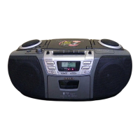
The devices covered by this manual are integrated audio systems designed for playing compact discs, receiving radio broadcasts, and playing/recording cassette tapes. They combine multiple audio sources into a single, portable unit, offering versatility for personal listening and entertainment.
The CD player section is capable of playing standard compact discs. It utilizes a semiconductor laser for scanning the disc, ensuring accurate data retrieval and playback. The CD mechanism, specifically the KSM-213CDM, is a core component for disc handling and laser operation.
The radio section supports both FM and AM frequency bands. Users can tune into their preferred radio stations using the built-in rod antenna for FM and a ferrite bar antenna for AM, ensuring reception across different broadcast types. The tuner section allows for frequency selection and signal processing to deliver clear audio.
The cassette deck section is a full-featured component for cassette tape playback and recording. It employs a 4-track, 2-channel format, which is standard for stereo cassette tapes. The recording system utilizes AC bias, a common method for improving recording quality by reducing distortion and noise. For erasing previously recorded material, a magnet erase system is incorporated. The deck is equipped with dedicated recording/playback heads and an erasure head to facilitate both functions. The basic tape mechanisms, TN-21ZVC-1759 and TN-51RV-233, are central to the cassette deck's operation, handling tape movement and head engagement.
The overall system includes speakers for audio output, allowing for stereo sound reproduction. Additionally, a headphones jack is provided for private listening, accommodating standard stereo mini-jack connections. The power requirements for these devices are flexible, allowing operation from either DC 12V using eight size C (R14) batteries for portability or AC power via a power cord. Some models, like the LH, offer switchable AC voltage (110-120V/220-240V) for international use, while others, like the U1, are fixed at AC 120V.
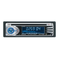
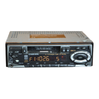
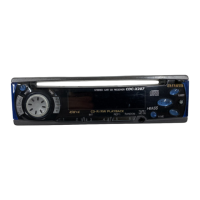
The front panel of the device features a LCD display that provides visual feedback to the user, showing information such as radio frequency, CD track number, and other operational statuses. The display is supported by an IC, LC71231, which controls its segments and indicators.
User interaction is primarily through a series of tactile switches on the front control board. These switches are labeled for various functions, including:
Some models may also feature a REMOTE CONTROL functionality, allowing for convenient operation from a distance. The internal IC, LC587008-1K43, plays a crucial role in managing system control, including processing inputs from the key matrix, controlling the LCD display, and managing various audio functions like mute, bass, and surround sound.
The device also incorporates LED indicators on the LED control board. These LEDs provide visual cues for operational status, such as FM/STEREO reception, Q SOUND activation, BASS enhancement, and OPE/BATT/FWD/REV status, which likely indicates power, battery, and cassette deck direction.
This service manual is designed to assist technicians in diagnosing and repairing the devices. It includes detailed electrical main parts lists and mechanical parts lists, providing part numbers and descriptions for all components. This is crucial for identifying and ordering replacement parts.
The manual emphasizes safety precautions regarding laser beam exposure during servicing of the CD player. It explicitly warns against direct eye exposure to the laser exit and advises observing from a distance of more than 30cm from the objective lens of the optical pick-up block. This highlights the importance of safety protocols when working with laser-emitting devices. Additionally, it provides guidance on handling the optical block (KSS-213C) to prevent electrostatic discharge (ESD) damage to the laser diode, recommending grounding the body and workbench.
Electrical adjustment procedures are outlined for both the tuner and deck sections. These procedures detail the steps for calibrating various parameters, such as AM IF adjustment, AM VT adjustment, AM tracking adjustment, FM VT adjustment, FM tracking adjustment, DC balance/mono distortion adjustment, FM auto stop level adjustment, tape speed adjustment, and azimuth adjustment. These adjustments are critical for ensuring optimal performance of the radio and cassette functions. Test points and specific settings are provided to guide technicians through the calibration process.
The manual also includes schematic diagrams and IC block diagrams for the main circuit boards (Main C.B, QX C.B, VR C.B, CD Main C.B, Front C.B, LED C.B, PT/BATT C.B, Motor-1 C.B). These diagrams illustrate the interconnections between components and the internal logic of integrated circuits, aiding in troubleshooting and understanding circuit operation.
Furthermore, transistor illustrations are provided to help identify different transistor types and their pin configurations (ECB, BCE, GSD, E), which is useful for component replacement. The "REFERENCE NAME LIST" is a valuable resource for clarifying descriptions of parts that may not be immediately understandable, ensuring accurate identification of components.
The manual also notes that connectors are not stocked as initial order items but are available upon order from manufacturers, which is an important logistical detail for parts procurement. This comprehensive approach to documentation ensures that technicians have all the necessary information to effectively service and maintain these Aiwa audio systems.
| Type | Car Receiver |
|---|---|
| Brand | Aiwa |
| Model | CSD-ED78 |
| CD Player | Yes |
| MP3 Playback | Yes |
| USB Port | Yes |
| Auxiliary Input | Yes |
| Bluetooth | No |
| Remote Control | Yes |
| Display | LCD |
| Power Output | 4 x 50W |