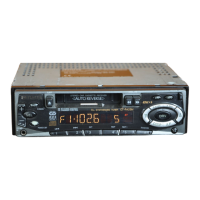
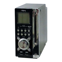
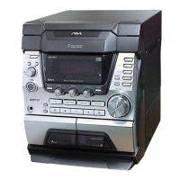
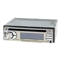
This document is a service manual for a stereo car cassette receiver, specifically for the AIWA CT-X310, CT-X325, CT-X320, CT-X4100, and CT-X4150 models. The manual provides detailed information for servicing and maintaining these devices, covering electrical and mechanical parts, as well as schematic diagrams.
Function Description
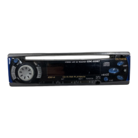
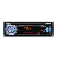
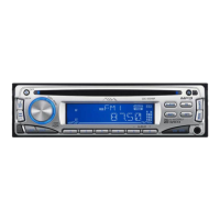
The devices covered are stereo car cassette receivers, indicating their primary function is to play audio cassettes and receive radio broadcasts within a vehicle. The "STEREO" designation implies a two-channel audio output for an immersive listening experience. The "CAR CASSETTE RECEIVER" specifies its intended use in automobiles, integrating both cassette playback and radio reception capabilities. The inclusion of a "BASIC TAPE MECHANISM: CDS-363AG1-A" suggests a standard tape transport system for these models, likely featuring functions such as play, fast forward, rewind, and possibly auto-reverse, although this is not explicitly stated. The schematic diagrams (SCHEMATIC DIAGRAM-1 and SCHEMATIC DIAGRAM-2) further illustrate the internal circuitry, including components for audio processing, radio tuning, and display control. The presence of an LCD (LCD901 AKT-16-17) indicates a digital display for showing information such as radio frequency, time, or cassette status.
Important Technical Specifications
While specific performance metrics like output power or frequency response are not detailed in the provided excerpts, the parts lists offer insights into the underlying technology and components.
- Microcontrollers and Processors: The presence of ICs like KIA6225S, TC9297FB, TC9323F-XXX, LC75374E, and TA8259H suggests sophisticated digital control and audio processing. The TC9297FB is likely a display controller, given its connection to the LCD901 and various segment/common lines (S1-S39, COM1-COM3). The TC9323F-XXX and LC75374E could be related to audio signal processing, tuning, or system control. The TA8259H is typically an audio power amplifier, indicating the device's capability to drive speakers.
- Tuner Unit: The "TU UNIT, FAE347-P10" (for CT-X310/325/4100/4150) and "TU UNIT, FAE347-A11/A12" (for CT-X320) are critical components for radio reception, suggesting different tuner modules across the model range. The "VIB,XTAL 4.5MHZ AT-49" (X701) is a crystal oscillator, essential for precise frequency generation in the tuner or microcontroller.
- Display Technology: The LCD (AKT-16-17) is a key user interface component. The schematic for SCHEMATIC DIAGRAM-2 shows a detailed segment display layout (FM123, MW, LW, PM, 88:88), indicating the ability to display radio bands, frequency, and time.
- Power Management: Various capacitors (e.g., ELECT 10-16SME, ELECT 47-16 SME, ELECT 100-10V, ELECT 220-10V, ELECT 3300U-16 PW) and diodes (e.g., 1N4002, 1SS133, ZENER MTJ6.2B, ZENER MTZJ10B, ZENER MTZJ6.8B, ZENER MTZJ9.1B, 1N5402) are used for power filtering, regulation, and protection. The "CAP,E 3300U-16 PW" (C608) is a large electrolytic capacitor, likely for power supply smoothing, indicating a robust power stage.
- Input/Output: Connectors such as "CONN, 16P SOC017" (CN201), "CONN ASSY, 3P HEAD" (CNA301), "CONN ASSY, 8P MOTOR" (CNA302), "CONN,15P CAM-B67" (CN901, CN801), and "JACK, PIN 4P XR-401" (J501) and "JACK, PIN 2P XR-401" (J501) indicate various connections for power, motor control, display, and external audio sources (AUX-R, AUX-L, A-GND). The "JACK, 3.5 BLK ST W/SW" (J901) suggests a standard 3.5mm stereo jack with a switch, possibly for headphone output or an auxiliary input sensing.
- Switches and Controls: A variety of switches are listed, including "SW,T CT 6X3.5 160" (S901-S910, S913), "C-SW,TACT SKQMAL" (S905, S911, S912, S915, S916), and "SW,SL 1-1-2 SSSS212-11-A" (S751). These indicate tactile switches for various functions like power, mode selection, tuning, and volume control. The "SW,RTRY SIM-026MT" (VR901) is likely a rotary encoder or switch, possibly for volume or menu navigation.
Usage Features
The parts list and schematic diagrams reveal several user-facing features:
- Digital Display: The LCD (AKT-16-17) with its segment layout (FM123, MW, LW, PM, 88:88) provides clear visual feedback for radio frequency, band (FM, MW, LW), and time.
- Illumination: The presence of "C-LED, SEC 1201C RED" (D907-D909) and "C-LED, SEC1E01C BLUE" (D910-D912) indicates backlighting or indicator lights, enhancing visibility and user experience, especially in a car environment. The "CAP, LAMP BLU B" (8Z-KT1-239-010) suggests a blue lamp for additional illumination.
- Control Buttons: Numerous buttons are listed, including "BTN, PWR," "BTN, DISP," "BTN, A/M," "BTN, LO," "BTN, INFO," "BTN, EJECT," "BTN, FF," "BTN, REW," "BTN, FNC," "BTN, DETACH," "BTN, UP/DN," and "BTN,P.SET." These provide direct access to various functions such as power on/off, display mode, auto/manual tuning, local/distance reception, information display, cassette eject, fast forward, rewind, function selection, detachable faceplate release, up/down navigation, and preset station setting.
- Rotary Control: The "SW,RTRY SIM-026MT" (VR901) suggests a rotary control, commonly used for volume adjustment or menu navigation, offering a tactile and intuitive user interface.
- Auxiliary Input: The "AUX-R" and "AUX-L" lines on CN901, along with the 3.5mm jack (J901), strongly suggest an auxiliary audio input feature, allowing users to connect external audio devices like smartphones or MP3 players.
- Detachable Faceplate: The "BTN, DETACH" and "LEVER, DFP LOCK -T10" (8Z-KTA-203-010) and "LEVER, DEF HOOK -T10" (8Z-KTA-204-110) indicate a detachable faceplate security feature, common in car stereos to deter theft.
- Speaker Outputs: The "SPKR, 13CM ASSY" (8A-KTG-951-010) and "SPKR, 16CM ASSY" (8Z-KTG-951-010) in the accessories list suggest that speakers might be bundled with certain models or are compatible accessories.
Maintenance Features
The service manual itself is a primary maintenance feature, providing comprehensive information for technicians.
- Detailed Parts Lists: The "ELECTRICAL MAIN PARTS LIST" and "MECHANICAL PARTS LIST" provide a complete breakdown of all components, including their part numbers, descriptions, and suffixes indicating model compatibility. This is crucial for identifying and ordering replacement parts.
- Schematic Diagrams: "SCHEMATIC DIAGRAM-1" and "SCHEMATIC DIAGRAM-2" offer a visual representation of the internal circuitry, enabling technicians to trace signal paths, identify faulty components, and understand the device's operational logic.
- Revision Publishing: The note "• Replace this Service Manual with "Revision Publishing" when it is issued." indicates a commitment to providing updated information, ensuring that maintenance personnel always have access to the latest service procedures and component data.
- Standardized Components: The use of many common electronic components (e.g., 1N4002 diodes, various types of capacitors, standard transistors) simplifies sourcing and replacement.
- Modular Design: The presence of "TU UNIT" (tuner unit) as a distinct component suggests a modular design, potentially allowing for easier replacement of major functional blocks.
- Connectors: The extensive use of connectors (e.g., 16P SOC017, 3P HEAD, 8P MOTOR, 15P CAM-B67) facilitates disassembly and reassembly, making it easier to access and replace internal components without extensive soldering.
- Screws and Fasteners: The inclusion of various screws (e.g., "S-SCREW, THIN HEAD+2.6-4 BLK," "S-SCREW, PT 28 BH+ BLK," "S-SCREW, 56 TH+ TAPPING ST") in the mechanical parts list ensures that technicians have the correct fasteners for reassembly, preventing damage from incorrect screw types.
In summary, the AIWA CT-X series stereo car cassette receivers are designed for in-vehicle audio entertainment, featuring both cassette playback and radio reception with a digital display, various control buttons, and potentially an auxiliary input. The service manual provides extensive documentation to support maintenance and repair, emphasizing component-level troubleshooting and replacement.