1
Ver 1.0 2004. 01
Model Name Using Similar Mechanism CDX-R3000/R3000T
CD Drive Mechanism Type MG-611XC-186//Q
Optical Pick-up Name KSS1000E
SERVICE MANUAL
US Model
Canadian Model
CDC-X104/X144
AEP Model
UK Model
CDC-R104/X104
CDC-R104/X104/X144
AUDIO POWER SPECIFICATIONS (US MODEL)
POWER OUTPUT AND TOTAL HARMONIC DISTORTION
22 watts per channel minimum continuous average power into
4 ohms, 4 channels driven from 20 Hz to 20 kHz with no more
than 5% total harmonic distortion.
Tuner section
FM
Tuning range US, Canadian Model:
87.5 – 107.9 MHz
AEP, UK Model:
87.5 – 108 MHz
Antenna terminal External antenna connector
Intermediate frequency 10.7 MHz/450 kHz
Usable sensitivity 9 dBf
Selectivity 75 dB at 400 kHz
Signal-to-noise ratio 67 dB (stereo),
69 dB (mono)
Harmonic distortion at 1 kHz
0.5% (stereo),
0.3% (mono)
Separation 35 dB at 1 kHz
Frequency response 30 – 15,000 Hz
AM (US, Canadian Model)
Tuning range 530 – 1,710 kHz
Antenna terminal External antenna connector
Intermediate frequency 10.7 MHz/450 kHz
Sensitivity 30 µV
MW/LW (AEP, UK Model)
Tuning range MW: 531 – 1,602 kHz
LW: 153 – 279 kHz
Antenna terminal External antenna connector
Intermediate frequency 10.7 MHz/450 kHz
Sensitivity MW: 30 µV
LW: 40 µV
CD player section
Signal-to-noise ratio US, Canadian Model: 110 dB
AEP, UK Model: 120 dB
Frequency response 10 – 20,000 Hz
Wow and flutter Below measurable limit
SPECIFICATIONS
Power amplifier section
Outputs Speaker outputs
(sure seal connectors)
Speaker impedance 4 – 8 ohms
Maximum power output 45 W × 4 (at 4 ohms)
General
Outputs Audio outputs terminal (rear/sub switchable)
Power antenna relay control terminal
Power amplifier control terminal
Inputs Telephone ATT control terminal (AEP, UK Model)
Antenna input terminal
Tone controls Low: ±10 dB at 60 Hz (HIP-HOP)
Mid: ±10 dB at 1 kHz (HIP-HOP)
High: ±10 dB at 10 kHz (HIP-HOP)
Power requirements 12 V DC car battery (negative ground)
Dimensions Approx. 178 × 50 × 176 mm
(7 1/8 × 2 × 7 in.) (w/h/d)
Mounting dimensions Approx. 182 × 53 × 161 mm
(7 1/4 × 2 1/8 × 6 3/8 in.) (w/h/d)
Mass Approx. 1.2 kg (2 lb. 10 oz.)
Supplied accessories Parts for installation and connections (1 set)
Front panel case (1)
Design and specifications are subject to change without
notice.
• The tuner and CD sections have no adjustments.
Sony Corporation
e Vehicle Company
Published by Sony Engineering Corporation
9-877-520-01
2004A04-1
© 2004. 01
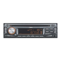
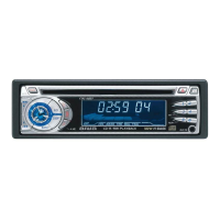
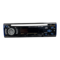
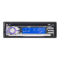
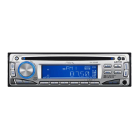
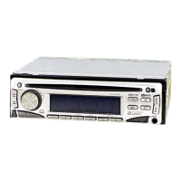
Photo: CDC-X104
FM/AM COMPACT DISC PLAYER
US, Canadian model
FM/MW/LW COMPACT DISC PLAYER
AEP, UK model