Do you have a question about the Aiwa AD-F990 and is the answer not in the manual?
Guidelines for safe and effective service procedures and repairs.
Key procedures for maintaining and repairing the cassette mechanism.
Detailed description and functions of microcomputer terminal IC-1.
Detailed description and functions of microcomputer terminal IC-2.
Detailed description and functions of microcomputer terminal IC-3.
Further detailed pin descriptions for microcomputer terminal IC-3.
Overall block diagram illustrating the AD-F990 system architecture.
Explanation of the auto Dolby-NR selector system and its operation.
Detailed description of the Low Pass Filter (L.P.F.) circuit.
Description of the tone and decoder IC circuit.
Description of the Analog Switch circuit.
Description and function of the shaper circuit.
Details on how the Dolby NR circuit is controlled.
Explanation of recording and playback operations, including Dolby NR modes.
Overview of the control system's behavior during recording.
Description of automatic operation during tape playback.
Details on different playback modes and their operations.
Explanation of Tape Selector (T/S) functions and selection.
Description of the automatic tape monitor system.
Procedure for adjusting the automatic recording level using electronic VR.
Detailed pin description for the TC9153P IC.
Detailed explanation of the functions for each pin of IC5V.
Block diagram illustrating the internal structure of the TC9153P IC.
Graph showing the relationship between VR position and attenuation value.
Detailed description of the Electronic VR IC (IC5V) and its operation.
Procedure for manual DOWN operation of the VR.
Explanation of the AUTO circuit's operation.
Description of the AUTO circuit operation after peak detection.
Explanation of the peak detector circuit's operation.
Details on the operation of the VR position indicator circuit.
Timing chart for automatic operation of the unit.
Timing chart illustrating the UP operation sequence.
Timing chart illustrating the DOWN operation sequence.
Description of FL bar meter, drive IC, peak hold, single bar PEAK, and FL OSC circuits.
List of components and connectors for various circuit boards.
Important precautions for handling C-MOS integrated circuits.
Detailed descriptions of specific circuit sections.
Explanation of symbols used in the diagrams.
Procedures for Compu-Brain, Bias OSC frequency, and Bias Trap adjustments.
Procedures for Playback characteristics, sensitivity, LH REC/PB, and METAL EQ adjustments.
Procedures for AUTO DOLBY and REC VR level indication adjustments.
Diagrams illustrating the internal wiring of the unit.
Procedures for Tape Speed, Erase Head, and Azimuth adjustments.
Description of the Auto Volume Level circuit.
Description of the circuit related to timing charts.
| Brand | Aiwa |
|---|---|
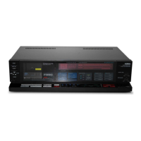
| Model | AD-F990 |
| Category | Car Receiver |
| Language | English |