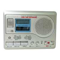
Do you have a question about the Aiwa TP-S90 and is the answer not in the manual?
General instructions and warnings for safe repair procedures.
List of Integrated Circuits used in the main board.
List of transistors used in the main board.
List of diodes used in the main board.
Parts list for the Main Circuit Board.
Parts list for the Switch Circuit Board.
Parts list for the RP Head Flex Circuit Board.
Parts list for the E Head Flex Circuit Board.
Visual representation of transistor pin configurations.
Explanation of the part coding system for chip resistors.
Visual representation and pinout of the LCD display.
Functional block diagram of the main IC (LB1977M-TLM).
Wiring connections for Main, RP Head, and E Head Flex boards.
Wiring connections for the Switch Circuit Board.
Detailed circuit schematic for the entire device.
Procedure for adjusting tape speed in normal mode.
Procedure for adjusting tape speed in 2x mode.
Detailed description of pin functions for the TC9318FB-061 IC.
Detailed description of pin functions for the LB1977M IC.
Diagram showing the assembly of mechanical parts.
Comprehensive list of all mechanical parts and their codes.
Diagram showing the assembly of the tape mechanism components.
Comprehensive list of all tape mechanism parts and their codes.
List of accessories and items included in the package.
| Noise Reduction | Dolby B |
|---|---|
| Inputs Line In | Yes |
| Inputs Mic In | Yes |
| Outputs Line Out | Yes |
| Type | Cassette Recorder |
| Recording Heads | 1 x Erase |
| Tape Type | Type I, CrO2, Metal |
| Wow and Flutter (WRMS) | 0.07% (WRMS) |