EasyManua.ls Logo

Aiwa XA-950 Service Manual

Aiwa XA-950
12 pages
To Next Page IconTo Next Page
Page #1 background imageLoading...
Page #1 background image
S/M
Code
No.0076
DATE
OF
ISSUE
7/1992
-—!
XA-950
aiica
SERVICE
MANUAL
STEREO
INTEGRATED
AMPLIFIER
SPECIFICATIONS
General
input
jacks
Power
requirements
(Sensitivity/input
impedance)
XA-950E,
Z
PHONO
:
MM
230V
AC,
50
Hz
2.5
mV/47k
ohms
XA-950K
:
ern
TUNER
eo
VEC
AI
oo
Power
consumption
:
;
es
WwW
TAPE
1,
TAPE
2/DAT,
Power
amplifier
ADAPTOR:
150
mV/47k
ohms
PHONO
overioad
level
130
mV
(MM)
Effective
output
power
(1
kHz,
T.H.D
0.01%)
150
W+150
W
Output
jacks
(4
ohms,
T.H.D.
0.9%,
(Level/output
impedance)
1
kHz)
TAPE
1,
TAPE
2/DAT,
100
W+100
W
ADAPTOR:
150
mV/47k
ohms
(8
ohms,
T.H.D.
0.9%,
Headphones:
8-32
ohms
1
kHz)
Speakers:
4-16
ohms
Total
harmonic
distortion
(A+B:
8-16
ohms)
0.005%
RIAA
deviation
+0.5
dB
(30
Hz—15
kHz)
(20
Hz-20
kHz,
75
W,
SUBSONIC
filter
8
ohms)
16
Hz
12
dB/Oct
Output
bandwidth
§
Hz—70
kHz
Maximum
dimensions
(less
than
0.05%)
(wihid)
430
x
140
x
340
mm
(Both
channels
driven,
(17
x
55/s
x
13/2
inches)
8
ohms)
Weight
10.5
kg
(23.1
Ibs)
Frequency
response
5
Hz~-150
kHz
(
dB)
Preamplifier
S/N
ratio
IHF
A
curve
short
circuited
PHONO
:
MM
95
dB
(5
mV
input}
-
MC
75
dB
@
Design
and
specifications
are
subject
to
change
without
notice.
(0.5
mV
input)
@
The
word
“BBE”
and
the
“BBE
symbol”
are
trademarks
of
BBE
TUNER,
CD,
VIDEO/AUX,
TAPE
1,
TAPE
2/DAT,
ADAPTOR:
110
dB
Sound,
Inc.
@
Under
license
from
BBE
Sound,
!nc.
AIWA
CO.,LTD.
Tokyo
Japan
Printed
in
Japan
Aooe
Question and Answer IconNeed help?

Do you have a question about the Aiwa XA-950 and is the answer not in the manual?

Aiwa XA-950 Specifications

General IconGeneral
Input Sensitivity2.5mV (MM), 150mV (line)
Channel Separation60dB (1kHz)
Output150mV (line)
Speaker Load Impedance4Ω to 16Ω
Phono InputMM/MC

Summary

Specifications

General, Power Amplifier, and Preamplifier Specs

Details power requirements, consumption, and amplifier/preamplifier specs like output power, distortion, bandwidth, and S/N ratio.

Input/Output, Filters, and Dimensions

Covers input/output jacks, RIAA deviation, subsonic filter, physical dimensions, and weight of the unit.

Electrical Main Parts List

Component Breakdown

Lists all major electronic components categorized by type: ICs, transistors, diodes, capacitors, resistors, fuses, jacks, coils, and relays.

Integrated Circuit Information

IC Block Diagram and Pin Details

Visualizes IC functions and provides pin-specific information for key integrated circuits.

Adjustment Procedures

Idling Current Adjustment

Step-by-step guide for setting idling current using test points and potentiometers for optimal performance.

Schematic Diagrams

Circuit Schematics for all Boards

Comprehensive schematics for all circuit boards including EQ, Volume, Front, Power Supply, and others.

Printed Circuit Board Layouts

Layouts for Main and Supporting Boards

Diagrams showing the physical layout of the main circuit board (A MAIN C.B) and other associated circuit boards.

Sub-Assembly Diagrams

Board Interconnections and Views

Illustrates how different circuit boards connect to the main unit and provides views of sub-assemblies.

System Block Diagram

Functional Unit Overview

High-level diagram showing functional blocks and signal flow of the amplifier system.

Exploded View - Mechanical Assembly

Component Identification in Assembly

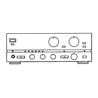
Diagram identifying major mechanical parts and their assembly within the unit.

Exploded View - Sub-Assemblies

Sub-Assembly Component Identification

Diagram identifying components within sub-assemblies and their mounting points.

Accessories and Package List

Included Accessories

Lists the instruction booklet and remote controls provided with the product.

Related product manuals