Do you have a question about the AJA KUMO Series and is the answer not in the manual?
Diagram illustrating the rear panel connections of the KUMO 3232 router, showing inputs, outputs, and control ports.
Details on connecting external power supplies (PS1 & PS2) to the KUMO unit for operation and redundancy.
Information on connecting the KUMO router to an Ethernet LAN for web server access and network control.
Explanation of the looping input for synchronizing KUMO timing with house video signals using analog or tri-level sync.
Description of connecting SDI video signals to the router's input and output BNC connectors in Normal Mode.
Explanation of how inputs and outputs utilize adjacent BNC pairs or groups for routed signals in different modes.
Details on the RS-422 DB-9 connector for serial connections and interoperability with other equipment.
Information regarding the RS-422 adapter required for older KUMO routers with serial numbers ending in -R0.
Overview of KUMO CP connections, featuring Ethernet and power supply ports but no BNC or RS-422 ports.
Guidance on direct-connecting KUMO router and CP via Ethernet for automatic system setup and operation.
Method for connecting KUMO routers to a network with a DHCP server for automatic IP assignment.
Techniques for network auto discovery, including Mac Bonjour and Windows UPnP for KUMO device connection.
Procedure to set KUMO devices to a temporary static IP address for direct connection and initial setup.
Overview of controlling multiple KUMO routers with KUMO CPs using web browser or network interfaces.
Information on supporting TCP-IP networking via DHCP or Static IP addressing for KUMO devices.
Steps to configure a fixed IP address, subnet mask, and default gateway in the KUMO UI Network screen.
How to select a KUMO device from the web interface's home screen dropdown menu for control.
Procedure to assign specific KUMO routers to control panel's Router Select buttons via the web page.
Using the web UI Identify button to locate physical KUMO routers or panels by flashing LEDs or buttons.
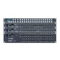
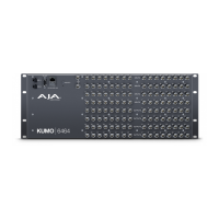
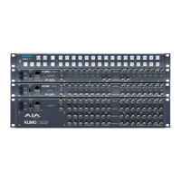
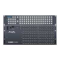
The AJA KUMO is a family of compact SDI routers designed for broadcast, production, and post-production environments. These routers provide flexible routing of SDI video signals, allowing users to connect various video sources to multiple destinations. The KUMO series offers different models, including the KUMO 1604, 1616, 3232, and 6464, which denote their input and output capacities.
At its core, the KUMO router functions as a central hub for SDI video signals. It takes multiple SDI video inputs and allows users to route any input to any output. This capability is crucial in professional video workflows where various cameras, playback devices, and processing equipment need to be interconnected and managed efficiently. The KUMO supports different SDI formats, ensuring compatibility with a wide range of professional video equipment.
The routing process can be controlled through several interfaces. Each KUMO device features a built-in web server, accessible via an RJ-45 Ethernet connection, which provides a comprehensive web-based user interface (UI). This UI allows for easy configuration, monitoring, and control of the router's crosspoints, source and destination naming, and network settings. For more direct control, AJA offers KUMO Control Panels (KUMO CP and KUMO CP2), which are hardware panels with physical buttons for source and destination selection. These control panels connect to the KUMO router via Ethernet and offer a tactile, immediate way to manage routing.
The KUMO routers also support external reference video (REF BNC connector) for synchronizing the crosspoint switch timing with house video signals. This ensures clean, glitch-free switching between sources, which is essential in live production and broadcast environments. The REF BNC connector is a looping input, allowing the reference signal to be passed through to other equipment.
For advanced control and integration into larger systems, KUMO routers include an RS-422 female DB-9 connector. This serial connection enables interoperability with other devices and supports the GVG Native Protocol, a common standard for controlling video routers. This allows the KUMO to be integrated into existing control systems or controlled by third-party applications.
The KUMO series supports different operating modes, including Normal, Dual, and Quad modes. In Normal mode, BNC inputs and outputs have a one-to-one relationship with the SDI signals. In Dual mode, adjacent pairs of BNCs are used for each routed signal, while in Quad mode, four adjacent BNCs are used. These modes cater to different signal types and bandwidth requirements, offering flexibility for various production needs.
The KUMO is designed for ease of use and flexible deployment. Power is supplied by an external 12 VDC power supply module, with redundant power supply connectors (PS1 and PS2) available for enhanced reliability, protecting against outages. The power connectors feature a latch mechanism, similar to Ethernet connectors, to ensure secure connections.
Initial setup can be simplified through several auto-configuration methods. If a KUMO CP is purchased with a KUMO router, a direct Ethernet connection between the two will trigger an Auto Configure function. The control panel will automatically set itself up to operate with the connected router, with buttons lighting up and routing becoming immediately available if SDI connections are made.
For network integration, KUMO routers support DHCP (Dynamic Host Configuration Protocol) by default. When connected to a DHCP-enabled network, the router will automatically obtain compatible IP network settings. This allows for quick integration into existing IT infrastructures. Alternatively, for environments requiring fixed network addresses, the KUMO supports static IP configuration, which can be set via the web UI.
Computer auto-discovery features further streamline network setup. Mac users can leverage Bonjour, built into the Safari browser, to auto-detect and connect to KUMO devices on the network. Windows PC users can utilize UPnP protocols and network discovery services to find and control KUMO routers from a device list in their Control Panel or File Explorer.
For direct access or troubleshooting, KUMO devices offer a factory default static IP address (192.168.101.1). This temporary static IP can be activated by pressing a recessed reset button on the router or by holding two SHIFT buttons on a control panel for five seconds. This feature provides a fail-safe way to connect to and configure the device, even if its network settings are misconfigured.
The web UI provides a comprehensive interface for managing the router. Users can name sources and destinations, configure network settings, and assign control panels to specific routers. The "Identify" button in the web UI is a useful feature for locating a specific KUMO device in a rack of equipment. When activated, the Identify LEDs on both the front and rear panels of the router will flash, or the Source and Destination buttons on a control panel will flash alternately, making physical identification quick and easy.
Maintenance of KUMO routers is primarily focused on software updates and network management. Firmware updates can be performed through the web UI, ensuring the device benefits from the latest features, bug fixes, and performance improvements.
The power loss recovery feature is a significant maintenance benefit. If a KUMO router experiences a power loss, it will return to its previous state of all source-to-destination crosspoints and retain all configured source and destination names once power is restored. Similarly, if a KUMO control panel loses power, its configuration and button tallies will return to their previous states upon power restoration. This minimizes downtime and simplifies recovery after unexpected power interruptions.
The redundant power supply connectors (PS1 and PS2) allow for the connection of an optional second power supply. This redundancy is a critical maintenance feature, as it provides a fail-safe mechanism against power supply failures, ensuring continuous operation in critical environments.
Network configuration flexibility, including DHCP and static IP options, simplifies ongoing network management. The ability to easily reconfigure network settings via the web UI or through auto-discovery mechanisms reduces the complexity of integrating KUMO devices into evolving network infrastructures. The recessed reset button on the router and the SHIFT button combination on the control panel provide a reliable way to revert to a temporary static IP, which is invaluable for troubleshooting network connectivity issues without requiring specialized tools or extensive network knowledge.
Overall, the AJA KUMO series is designed for robust, flexible, and user-friendly operation in professional video environments, with features that support both efficient daily use and straightforward maintenance.
| Type | Router |
|---|---|
| Network Interface | 10/100/1000 Ethernet |
| Redundant Power | Optional |
| Power Supply | 100-240V AC, 50/60Hz |
| Form Factor | 1RU, 2RU (depending on model) |
| Video Formats | SD, HD, 3G-SDI |