EasyManua.ls Logo

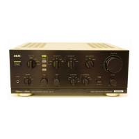
Akai AM 73 User Manual

Akai AM 73
34 pages
To Next Page IconTo Next Page
Page #1 background imageLoading...
Page #1 background image
Question and Answer IconNeed help?

Do you have a question about the Akai AM 73 and is the answer not in the manual?

Akai AM 73 Specifications

General IconGeneral
TypeIntegrated Amplifier
Power Output100 watts per channel into 8Ω (stereo)
Frequency Response5Hz to 100kHz
Damping Factor60
Output150mV (line)
Speaker Load Impedance4Ω to 16Ω
Input Sensitivity2.5mV (MM)
Signal to Noise Ratio86dB (MC), 96dB (MM)

Summary

Specifications

Safety Instructions and Information

Precautions During Servicing

Guidelines for safe and correct servicing procedures to prevent hazards.

Safety Check After Servicing

Procedures to confirm the set's safety after repairs are completed.

Front Panel Controls

Power and Input Selection Controls

Controls for powering the unit on/off and selecting input sources.

Volume and Tone Adjustment Controls

Controls for adjusting audio volume, bass, and treble levels.

Speaker and Headphone Controls

Controls for selecting speaker outputs and connecting headphones.

Rear Panel Connections

Digital and Analog Input/Output Jacks

Connectors for digital sources, analog audio signals, and tape decks.

Speaker Terminals and Power Input

Connections for speaker systems and the main power cord.

Disassembly Procedures

Internal Component Locations

Electrical Adjustment Procedures

Idling Current Adjustment

Procedure for adjusting the amplifier's idling current for optimal performance.

Phono Amplifier Off-set Adjustment

Procedure for setting the DC off-set voltage for the phono amplifier.

D/A Convertor Distortion Adjustment

Parts List Information

Recommended Spare Parts List

PC Board Identification

Final Assembly Diagram

Schematic Diagram Overview

Printed Circuit Board Schematics

List of detailed schematics for various printed circuit boards.

Integrated Circuit Schematics

Printed Circuit Board Schematics

Equalizer and DAC PCB Schematics

Detailed circuit diagrams for the Equalizer and DAC PC boards.

Input, Indicator, and Rec Selector PCB Schematics

Circuit diagrams for Input, Indicator, and Rec Selector PC boards.

Further PCB Schematics

Signal Path PCB Schematics

Equalizer and Input Selector PCB Schematics

Circuit diagrams for Equalizer and Input Selector PC boards.

Rec Selector and Tone Control PCB Schematics

Circuit diagrams for Rec Selector and Tone Control PC boards.

Detailed PCB Schematics

Main Amplifier PCB Schematics

Detailed circuit diagrams for the Main Amplifier PC board.

PCB Layouts and Component Locations

Main Amplifier PCB Layout and Components

Layout diagram and component identification for the Main Amplifier PCB.

PCB Layouts and Component Identification

Main Amplifier PCB Layout

Layout diagram and component identification for the Main Amplifier PCB.

Signal Path PCB Layouts

DAC PCB Schematic Diagram

DAC PCB Layout and Components

DAC PCB Schematic Details

Related product manuals