Do you have a question about the Akai AM-U3 and is the answer not in the manual?
Confirm insulation resistance after servicing for electrical safety.
Guidelines for safe component handling, wiring, and material usage during repairs.
Detailed technical specifications of the power amplifier and pre-amplifier sections.
Step-by-step instructions for disassembling the audio unit for servicing.
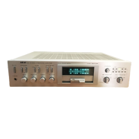
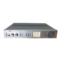
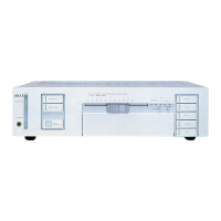
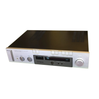
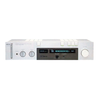
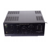
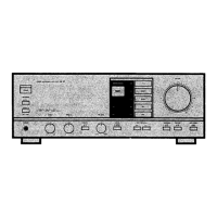
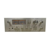
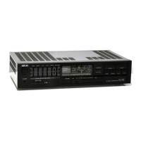
Identification and description of front and rear panel controls and connectors.
Block diagrams and functional explanation of the control IC and its associated circuitry.
Diagrams showing the physical location of key components and PCBs.
Procedure for adjusting the quiescent current for optimal amplifier performance.
List and identification of different printed circuit boards used in the unit.
Instructions on interpreting part numbers, classifications, and diagrams in the list.
A curated list of critical components recommended for stocking for repairs.
Detailed parts breakdown and reference numbers for the main amplifier circuit board.
Parts list and references for the equalizer circuit board.
Parts list and references for the power supply circuit board.
Parts list and references for the filter circuit board (V only).
Identification of major assembly units and their components.
Detailed diagram and parts list for the final external assembly of the unit.
Overall circuit diagram illustrating the electronic interconnections of the unit.
Detailed circuit diagrams for integrated circuits used in the unit.
| Power Output | 40 watts per channel into 8Ω (stereo) |
|---|---|
| Frequency Response | 5Hz to 100kHz |
| Total Harmonic Distortion | 0.05% |
| Input Sensitivity | 2.5mV (MM), 150mV (line) |
| Input Impedance | 47k ohms |
| Speaker Impedance | 4Ω to 16Ω |