EasyManua.ls Logo

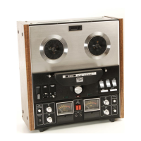
Akai GX-260D

Akai GX-260D
55 pages
To Next Page IconTo Next Page
To Previous Page IconTo Previous Page
Loading...
TAPE
SPEED
7
|
ips
<3dB
2KC
20KC.
23KB
Fig.
18
5.
FREQUENCY
RESPONSE
ADJUSTMENT
1)
Refer
to
section
regarding
Frequency
Response
Measuring
Method
(Fig.
3
of
this
manual).
2)
Adjust
REC
Amp.
P.C.
Board
semi-fixed
capaci-
tors
TC1,
TC2
(70P)
so
that
a
20
kHz
signal
output
level
is
the
same
in
relation
to
2,000
Hz.
(See
Fig.
18)
3)
The
Bias
Voltage
will
vary
depending
on
the
Recording
Head
and
tape
being
used.
.
NOTE
1)
The
frequency
response
will
vary
depending
upon
the
tape
being
used.
For
model
GX-260D,
Fuji
tape
F-100
is
used
for
frequency
response
adjust-
ment.
2)
Prior
to
adjustment,
record
at
non-signal
input
and
adjust
Bias
Trap
L1
(22
mH)
so
that
the
bias
leak
at
line
out
is
minimum.
(See
Fig.
15)
6.
ERASE
VOLTAGE
There
is
no
way
to
adjust
the
Erase
Voltage,
but
correct
value
is
about
35V
at
7-1/2
ips,
and
30V
3-3/4
ips.

Other manuals for Akai GX-260D

Related product manuals