EasyManua.ls Logo

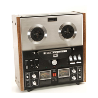
Akai GX-260D

Akai GX-260D
55 pages
To Next Page IconTo Next Page
To Previous Page IconTo Previous Page
Loading...
5.
TOTAL
HARMONIC
DISTORTION
GX-260D
Audio
Line
Frequency
input
Line
Oscillator
output
Distortion
Meter
Fig.
5
Connect
the
measuring
instruments
as
shown
in
Fig.
5
and
record
a
1,000
Hz
sine
wave
signal
at
“O”
VU.
Playback
the
resultant
signal
and
measure
the
over-
all
distortion
factor.
NOTE
1)
At
this
time,
Distortion
of
the
Audio
Fre-
quency
Oscillator
must
be.
sufficiently
small.
2)
When
measuring
the
distortion
factor,
new
tape
should
be
used.
6.
CROSS
TALK
(Cross
talk
between
the tracks)
TAPE
Fwo.
REV.
TAPE
DIRECTION
!
2
TAPE
DIRECTION,
3
4
Fig.
6
As
shown
in
Fig.
6,
first
record
a
1,000
Hz
sine-
wave
signal
on
track
No.
3
at
+3
VU
level.
Next,
record
under
a
non-input
condition.
Then
play-
back
the
tape
on
track
No.
3
and
(1)
(reversed
condition
of
tape)
through
the
B.P.F.
(1,000
Hz
Band
Pass
Filter,
sensitivity
1,000
Hz,
ratio
1:1)
and
obtain
the
ratio
from
the
following
formula.
2
Eo
C=20
log
"EL -E,
(dB)
where,
C
=Desired
cross
talk
ratio
(dB)
Eo
=1,000
Hz
signal
output
level
(V)
=a
E,
=1,000
Hz
cross
talk
level
(V)
ES
E,
=Non-input
cross
talk
level
(V)
_
EZZZ
7.
ERASE
RATIO
ban
-
TAPE
TAPE
4
2
77!
ser
4
Fig.
7
As
shown
in
Fig.
7,
using
a
virgin
tape,
first
record
a
1,000
Hz
sinewave
signal
at
+3
VU
level,
then
playback
this
recorded
signal
and
take
a
V.T.V.M.
reading
at
the
output
level.
Next,
erase
this
recorded
portion
and
playback
the
erased
part
through
the
B.P.F.
(1,000
Hz
sensitivity
1:1)
and
take
readings
of
the
erased
signal.
Obtain
a
ratio
between
the
two
from
the
following
formula:
=
Eo
Er
=20
log
"ED
—E,
(dB)
where,
Er
=Desired
erase
ratio
E
=
1,000
Hz
signal
output
level
(Vv)
E,
=Erased
1,000
Hz
signal
and
noise
level
(V)
E,
=Erased
noise
level
(V)
NOTE:
When
measuring
cross
talk.
and
erase
ratio
virgin
tape
should
be
used.

Other manuals for Akai GX-260D

Related product manuals