EasyManuals Logo

Akai GX-280 User Manual

Akai GX-280
20 pages
To Next Page IconTo Next Page
To Previous Page IconTo Previous Page
Page #4 background imageLoading...
Page #4 background image
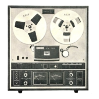
CONTROLS
Front
Panel
Controls
INDEX
COUNTER
For
use
in
locating
positiuns
un
a
tape.
With
Reset
Butzon,
se:
Index
Counter
to
“0000”
before
beginning
recording
cr
playback.
REEL
RETAINER
SUPPLY
REEL
TABLE
ees
RECORD
INDICATOR
LAMP
Recording
mode
indicator
lamp.
When
Record
and
Forward
Butcors
are
dapressed
(recording
mode
is
effected),
this
Record
Indicator
Lamp
witl
light.
TRACK
SELECTOR
BUTTONS
1-4/Sterco/3-2
Buttons
show
respective
markings
above
eack
button.
Easy
selection
of
proper
track
for
recording
or
playback
operation.
SENSING
POLE
(Left)
operation,
when
the
tape
is
being
reversed
from
[ao]
to
Fa],
During
Playha
such
autamatic
reverse
is
effected
when
the
sensing
tape
(affixed
to
the
magret-
ized
(ape
survace)
comes
in
contact
with
thia
sensing
pole.
SOUND
REFLECTOR
SPEAKER
(Left)
TENSION
ARM
Phe
'T
nsion
Arm
not
enly
works
to
correc:
tape
slack,
but
alo
stabilizes
tape
specd.
AAs
the
tape
adva:
zed
tersicn
is
applied
and
tape
vibration
is
climinated.
PAUSE
BUTTON
pe
Convenient
Jar
use
in
lemporarily
suspending
tape
movement
during
recording
or
playback
operativn.
‘Tuming
button
to
right
locks
it
ino
pause
position.
AUTOMATIC
SHUT-OFF
BUTTON
Shut-C17
Burton
is
linked
to
the
Automaric
ShuL-CF
Lever.
If
Phe
Autor
au
this
button
is
at
depressed
position,
when
the
tape
comes
to
the
end
or
is
broken,
the
power
of
the
entire
unit
is
cut
oll,
A
convenent
saicty
leature
in
case
the
recorder
is
left
unattended.
POWER
SWITCH
TAPE
SPEED
SELECTOR
BUTTONS
=
7-1/2
(19
cm/s)
and
3-3/4
(9.5
cm/s)
Speed
Selector
Butions.
Feather
touch
for
vasy
selection
of
desired
speed.
MICROPHONE
RECORDING
LEVEL
CONTROLS
(Left/Right)
When
using
microphones
for
reccrding,
acjast
input
with
these
cuntrols
while
pbucrving
VU
Meters,
MICROPIIONE
JACKS
(Left/Right)
When
using
microphones
for
recording,
insert
microphone
plugs
into
these
jacks,
Left
jack
is
for
left
channel
recording
and
right
jack
for
right
channel
recording,
HEADPHONE
JACK
LINE
RECORDING
LEVEL
CONTROLS
(Left/Right)
For
use
in
adjusting
line
recordiag
input
level.
Adjust
while
observing
VU
Meters.
VU
METERS
(Left/Right)
These
meters
indicate
revording
and
playback
levels
(Left
meter,
left
channel
level
and
right
meter,
right
channel
level).
Normal
recording
level
should
not
cacced
white
zuuc
uu
VU
Meters
(0
VU).
8.R.T.
SWITCID
t
Depress
when
using
AKAI
S.R/I.
(Super
Range
‘lape)or
other
make
low
noise
tapes.
TONE
CONTROLS
(Left/Right)
_—
a
——
ee
7
—s

Questions and Answers:

Question and Answer IconNeed help?

Do you have a question about the Akai GX-280 and is the answer not in the manual?

Akai GX-280 Specifications

General IconGeneral
BrandAkai
ModelGX-280
CategoryMeasuring Instruments
LanguageEnglish

Related product manuals