Door Control Unit User Manual
Updated until firmware 404p - 4 -
2x Brackets for rack mounting
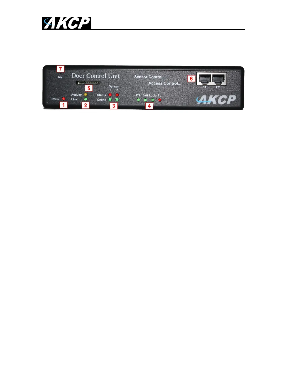
3) DCU Front and rear panels
Fig 1. Front panel
The front panel has several LEDs which display the DCU‟s status and notify you as to its activity.
1. Power LED
When the unit is powered up the power LED will be lit continuously.
2. Ethernet LED
Activity LED indicates the activity of the Ethernet port. Link indicates whether the
Ethernet link is 100 or 10 MBits/s
3. Sensors LED’s
The Sensors LED‟s indicates Error status and Online status of the 2 sensors ports.
4. Door LED’s
The Door LED‟s represent the status of the door:
- DS = Door status : always ON when door is closed, BLINK when door is opened,
or is held open, and FAST BLINK when door is forced open. (After v404p FWare)
- Exit = Exit Status: Turns OFF when exit is requested
- Lock = Door Relay status: Is ON when the relay is closed and BLINKS when the
relay is open.
- TP = Tamper status: is ON when the status is normal and BLINKS when the
status is critical.
5. SD Card slot
This slot is provided so you are able to add your own SD flash card to increase the
storage space on the unit. You can install up to a 16GB SD card.
The on board memory on the DCU is 128MB. This is where the operating system,
sensor data, the unit‟s settings, picture and sound logs are all stored if not stored on
the AKCess Control Server.
If the picture and sound logs become full they will then begin to be stored on your SD
card (if one is installed on the unit) automatically.
6. Expansion ports
 Loading...