Door Control Unit User Manual
Updated until firmware 404p - 5 -
There are two expansion ports numbered from E1 and E2. These are expansion
Ports for connecting either the 8-sensor8 or the E-opto16 expansion units. These are
also used for connecting the CCU or Cabinet Control Units. Please see each of these
separate user manuals for each of these products.
7. Mic
The mic is a small hole for access to the internal microphone. This can be used as a
sound sensor (or an external mic can be used)
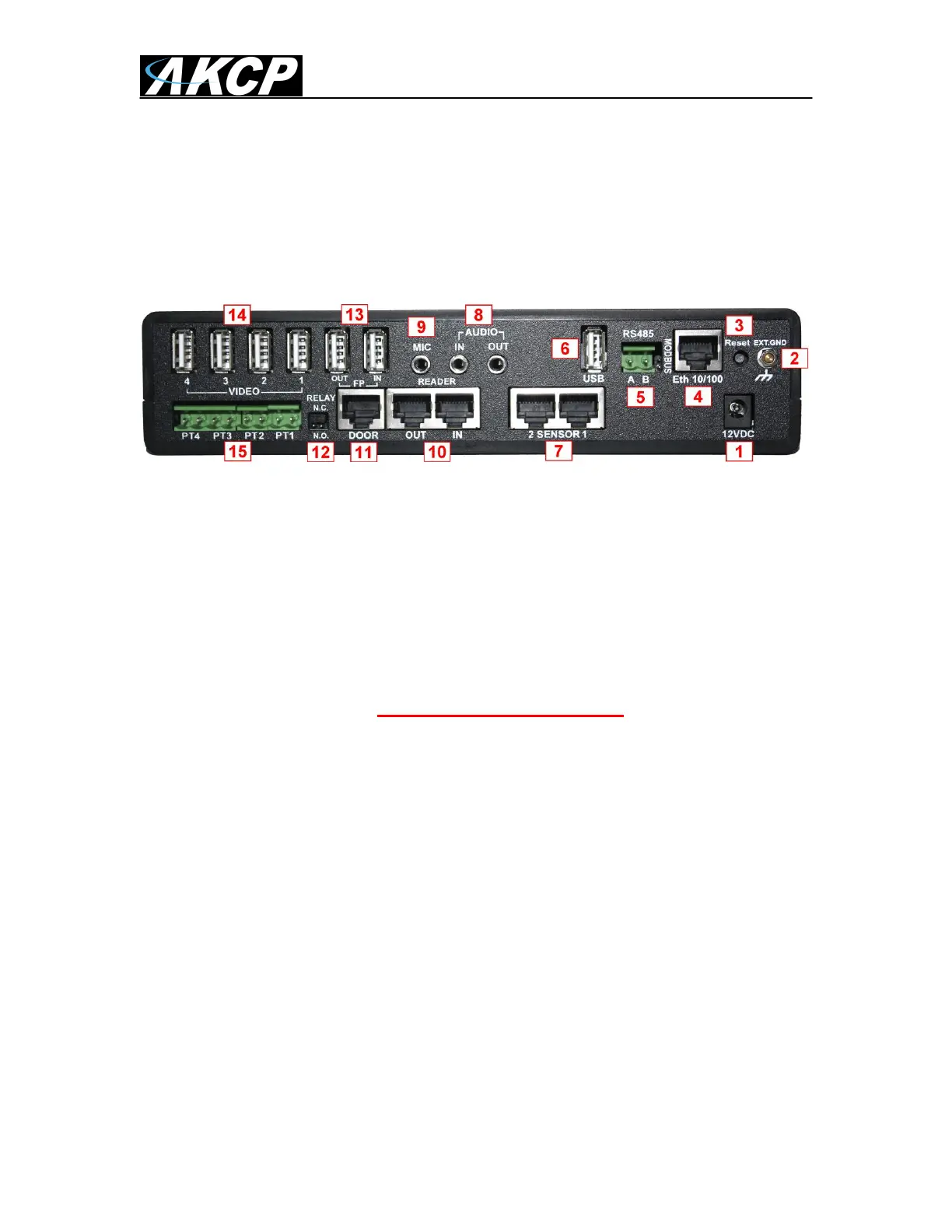
Fig 2. Rear panel
The rear panel of the DCU is home to various ports and connections. The functions of these are
as follows :-
1. 12VDC Power Input.
The 12 VDC power supply is connected to this input.
2. EXT GND
The External Ground is an option if you need to add an external ground connection to
the unit.
3. Safe Mode button. (DOES NOT RESET THE UNIT)
The black tact switch button is used to perform the following functions
A. A single press will announce the IP address of the unit. This is audible
through the internal speaker. It also broadcasts the IP address to the IPset
program.
B. Turns off password checking when accessing the web based interface (hold
down for 12 seconds)
C. To reboot the unit into the firmware upgrade or “SAFE” mode press and hold
in the button for more than 12 seconds.
4. Ethernet.
This RJ-45 connector is used for connecting the DCU to Ethernet network.
5. RS485 Port & 120Ohm Jumper
Used for Modbus connectivity. We support Modbus master or slave. When using the
DCU as a slave and the unit is the last device in the Modbus string the jumper (120
Ohm resister) needs to be jumpered at this connection.
 Loading...