SPX+ BEB Expansion Manual
- 6 -
SPX+ web UI configuration
With the 5VDC power supply connected first and the BEB unit(s) connected to the SPX+ BEB port,
you would fist open the SPX+ web UI and log in as Admin.
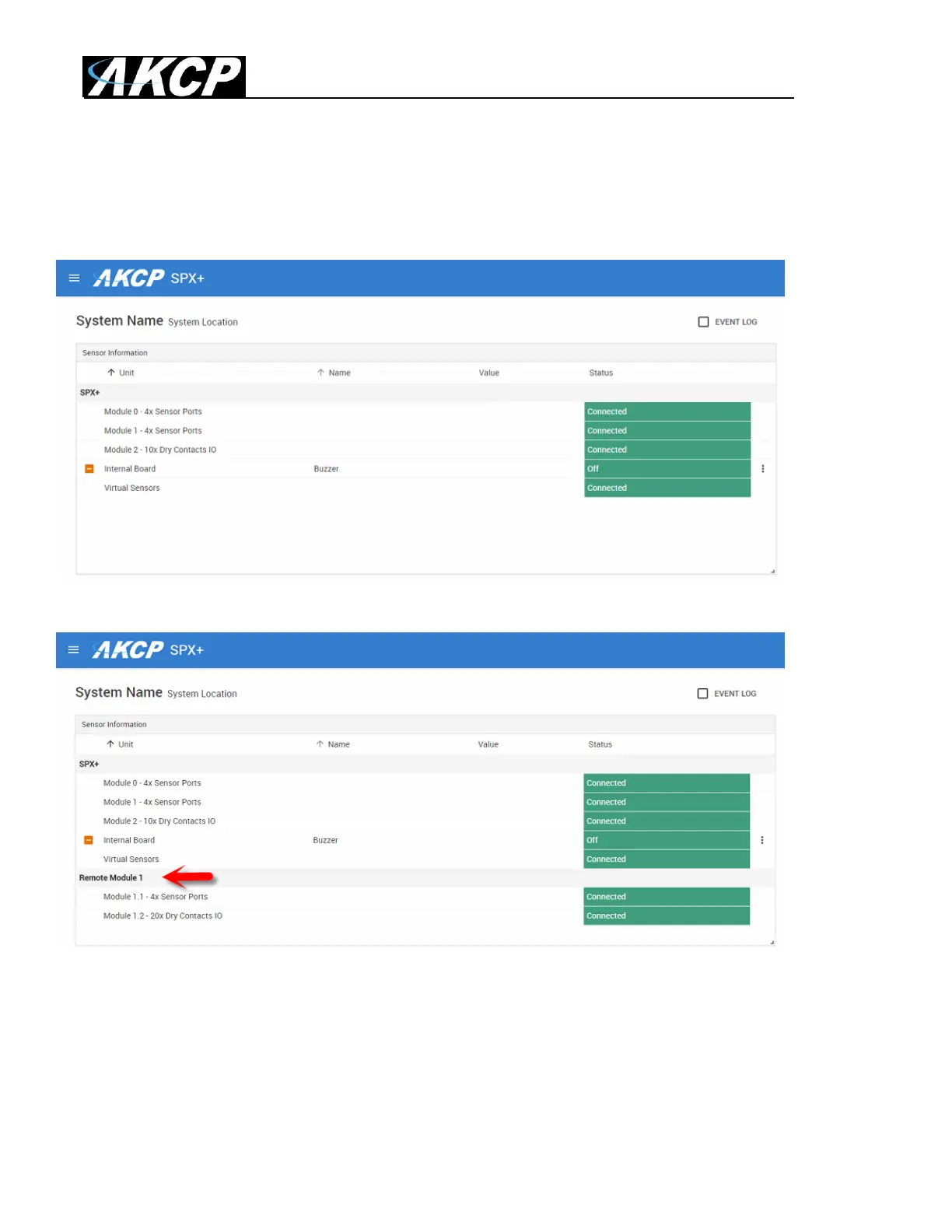
The screen shot above shows the SPX+ web UI before the BEB unit(s) are connected.
After connecting the BEB unit, this now appears as the “Remote Module” as you can see in the
screen shot above. Now the sensors and notifications and dry contacts can be configured normally.
Please refer to the SPX+ Manuals for detailed configuration of the sensors (the available options
match with the Web UI options). All AKCP type sensors are supported on the BEB slave units,
including the AKCP Swing Handle Locks.
 Loading...