\,
5. REPARATURANLEITUNG
5.1 . Zerlegen des Gerüfes:
o) Vergewissern Sie sich,
doß dos Neizkobel ouf keinen Foll mit
dem Neiz verbunden ist.
b) Entfernen
Sie
mit einem kleinen,
spitzen
Gegenstond oder dem
Fingernogel
die
groue
Abdeckung om Netzscholterknopf
(POWER
oN/oFF)
c) Lockern Sie
die
Schroube unter der Abdeckung
und entfernen Sie
den Knoof.
d) Entfernen
Sie
die
sechs
großen
Kreuzschlitzschrouben
on der Front-
olotte.
e) Nun
können Sie die Frontplotte,
gemeinsom
mii zwei
Scholtplorinen
ous dem Gehöuse ziehen und vor
dem
Gehöuse
oblegen.
f) Entfernen
Sie die vier Schrouben der Eingongs-/Ausgongs-Sfeckerplo-
tine, die
sich ouf der
Rückseite
des BX
5
befindet.
g)
Ziehen Sie
die
Netzteilploiine
ous dem Gehöuse.
h)
Um die
Holleinheit
ouszubouen, losen Sie
die
zwei
om Gehöuseboden
ongebrochten Schrouben
der
Befestigungswinkel.
Donn drücken
Sie die
Holleinheit
durch öffnungen in
der Gehöuserückwond noch
vorn'e ous
dem
Gehöuse.
Nicht
om Anschlußkobel ziehen
! !!
Beim
Wiedereinsetzen Gummiplöttchen
on der
Holleinheit
mit
etwos
Seife
gleitföhig
mochen.
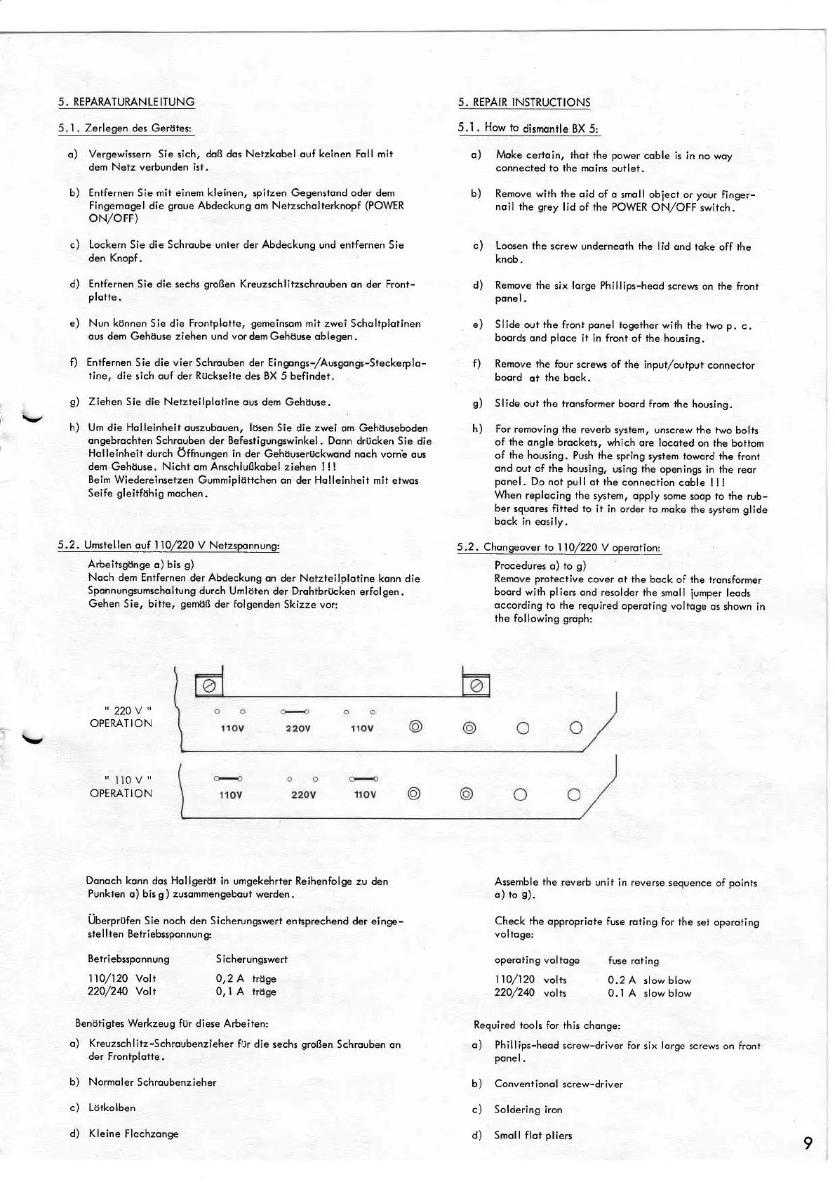
5.2.
Umstellen ouf
'l
l0/220
V
Netzsponnung:
Arbeitsgönge
o)
bis
g)
Noch
dem Entfernen
der Abdeckung
on der Netzteilplotine
konn die
Sponnungsumscholtung
durch
Umlöten
der
Drohtbrücken
erfolgen.
Gehen Sie, bilte,
gemöß
der folgenden
Skizze
vor:
"
220V
"
OPERATION
"ll0v"
OPIRATION
Donoch
konn dos
Hollgeröt
in umgekehrter Reihenfolge
zu den
Punkten
o) bis g
)
zusommengebout
werden.
Überprufen
Sie noch den Sicherungswert
entsprechend der einge-
ste
I lten
Betriebssponnun g:
5. REPAIR
INSTRUCTIONS
5.'I
.
How
to
dismontle BX 5:
o) Moke
certoin, thot the power
coble
is in no
woy
connected to ihe
moins
outlet.
b) Remove
with the oid
of o
smoll obiect or your
finger-
noil ihe
grey
lid of the POWER
ON/OFF switch.
c)
Loosen the
screw underneoth the
lid
ond toke
off
the
knob,
d) Remove
the
six
lorge
Phillips-heod
screws on the
front
ponel.
e) SIide
out
the
froni
ponel
togefher
wifh the
two p.
c.
boords
ond
ploce
it in front
of
the
housing.
f) Remove
the four
screws
of
the
inpui/output
connecror
boord
ot
the bock.
S)
Slide
out
fhe tronsformer
boord
from the
housing.
h)
For removing the
reverb
system, unscrew fhe two
bolts
of the ongle
brockets,
which
qre
locoted
on the botiom
of
the
housing.
Push the
spring sysiem toword the
front
ond out of the housing,
using
fhe
openings
in the
reor
ponel. Do
not
pull
ot the
connection
coble
! ! !
When
replocing the
system, opply
some
soop
to the
rub-
ber
squores fitted to
it in order to moke
the
sysfem
glide
bock in
eosily.
5.2. Chongeover to
I l0/220
V operotion:
Procedures
o)
to
g)
Remove
protective
cover oi the bock
of the tronsformer
boord
with pliers
ond resolder the
smoll
iumper
leods
occording
to the
required operoting
voltoge
os
shown in
the following groph:
Benötigtes
Werkzeug für diese Arbeiten:
o)
Kreuzschlitz-Schroubenzieher
fur
die sechs
großen
Schrouben on
der Frontplofte
.
b) Normoler
Schroubenzieher
c) Lotkolben
d) Kleine
Flochzonge
Assemble the
reverb
unii in reverse
sequence
of
poinfs
o) to
s).
Check
the oppropriote
fuse
rofing for the
sef operoting
voltoge:
operoiing
voltoge
fuse rofing
I
10l120
volts 0.2 A
slow blow
220/240
vol+s
0.1 A
slowblow
Required tools
for this chonge:
o)
Phillips-heod
screw-driver for six lorge
screws on fronl
ponel.
b) Conventionolscrew-driver
c) Soldering
iron
d)
Smoll flot
pliers
Betriebssponnung
110/120 Volt
220/2&
Yolt
S icherungswert
0,2 A trtige
0, I A
hage
9
 Loading...