Do you have a question about the AKG C 5900 and is the answer not in the manual?
Safety regulations and ground lead requirement for equipment connection.
Check packaging for all listed components upon receiving the microphone.
Details on optional accessories such as cables, windscreens, and stand adapters.
Key features including frequency response, pop filter, bass cut, and selectable output levels.
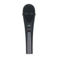
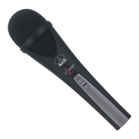
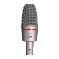
Detailed description of the AKG C 5900M/TM 40 microphone, its components, and functionality.
Condenser microphone requires power supply and provides balanced output on XLR connector.
Connecting the microphone to a balanced input using phantom power.
Connecting the microphone without phantom power using an optional supply.
Connecting the microphone to an unbalanced input using a specific cable configuration.
Instructions for removing the XLR connector module to install the TM 40 transmitter.
Hints on shaping vocal sound for best results with the microphone.
How working distance affects vocal sound and the impact of proximity effect.
Recommended microphone positions for optimal sound and breath noise reduction.
Understanding and preventing audio feedback using microphone polar pattern and placement.
Guidance for multiple vocalists sharing a microphone to avoid feedback issues.
Instructions for cleaning the surface of the microphone body with a soft cloth.
Procedure for removing, washing, and drying the internal windscreen.
Possible causes and remedies for the microphone producing no sound.
Causes and solutions for audio distortion issues with the microphone.
Troubleshooting dull sound by cleaning internal or external windscreen.
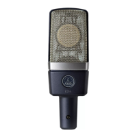
| Type | Condenser |
|---|---|
| Polar Pattern | Cardioid |
| Frequency Response | 20 Hz - 20 kHz |
| Connector | XLR |
| Preattenuation Pad | No |
| Bass Cut Filter | No |
| Power Requirements | 48V Phantom Power |
| Impedance | 200 ohms |
| Max SPL | 140 dB |
| Powering | 48V Phantom Power |
| Recommended Load Impedance | >=1000 Ohms |