REMARK: If no key is pressed for 25 seconds in either of the previous steps, the controller
will automatically return to the CURRENT TEMPERATURE display status without modifying
any of the parameters values.
Values in the Def. column are factory-set.
6- Description of parameters and messages
REMARK: When time parameters are modified, the new values are applied when the current
cycle is completed. In order for it to have an immediate effect, switch the controller off and
then on again.
Password request to enter programming parameters or SET POINT
It indicates defrosting is being carried out. In order to display "dEF" during defrosting,
it is essential that parameter d2 is set to option 2.
Parameters received from the parameters server.
Sensor failure (Open circuit, crossed, NTC: temp.> 110ºC or temp.<-55ºC
PTC: temp.> 150ºC or temp.<-58ºC)
Memory failure
MESSAGES
PA
dEF
CPY
E1
EEE
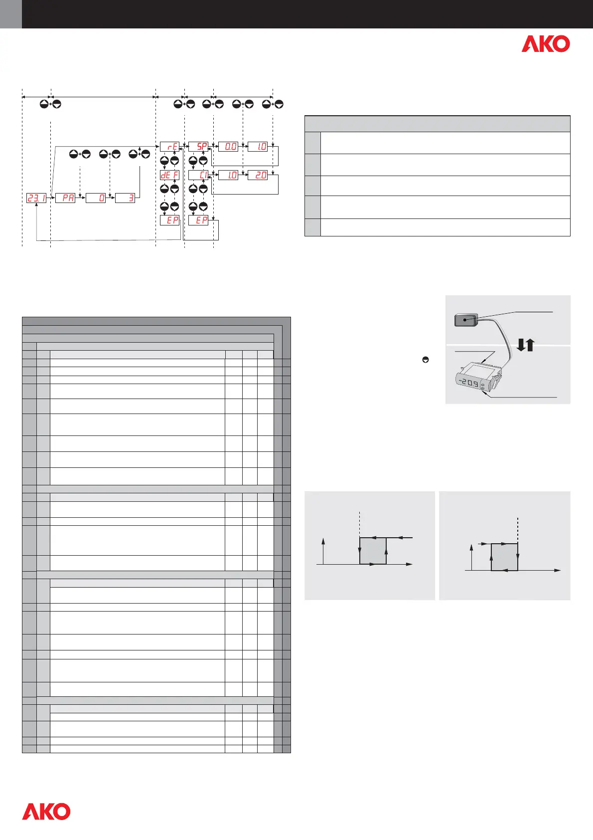
7- Parameters transfer
Portable server
AKO-14918 portable server, with no power
supply, in which parameters programmed in
a powered controller can be copied by
transfer. Parameters can be transferred again
from the server to other identical powered
controllers.
Storage dump or fast copy of the
parameters entered in the portable
server to the controller: Press the key
while the controller is being connected to
the power supply until the display shows
CPY, indicating that the transfer was made
correctly. Disconnect the controller and
reconnect it to the power supply.
Storage dump can also be done from
parameter L6=2.
Programming
AKO-14918
Power supply
Transfer
8- Relay operation and control
Clean the controller surface with a soft cloth, soap and water. Do not use abrasive detergents,
petrol, alcohol or solvents.
9-Maintenance
The use of the unit without observing the manufacturers instructions may alter its safety
qualification.
To ensure correct operation of the apparatus, only NTC or PTC type probes supplied by AKO
should be used.
Between 40 ºC and +20 ºC, when the NTC probe is extended up to 1.000 m with minimum
0,5 mm² cable, deviation will be less than 0.25 ºC (Probe extension cable ref. AKO-15586).
Operation for COLD (P0=0)
Operation for HEAT (P0=1)
OFF
ON
TEMP.
SET
POINT
C1
TEMP.
OFF
ON
C1
SET
POINT
10-Warnings
Av. Roquetes, 30-38 | 08812 Sant Pere de Ribes | Barcelona | España
Tel. (34) 938 142 700 | Fax (34) 938 934 054 | e-mail: ako@ako.com |
www.ako.com
Apartado (P.O. Box), 5 | 08800 Vilanova i la Geltrú | Barcelona | España
Nos reservamos el derecho de suministrar materiales que pudieran diferir levemente de los
descritos en nuestras Hojas Técnicas. Información actualizada en nuestra web: www.ako.com.
AKO ELECTROMECÀNICA, S.A.L.
351412302 REV.00 2008 D.L. B-18592-2008
we make it easy
we make it easy
AKO-14012, AKO-14023
AKO-14112, AKO-14120, AKO-14123, AKO-14125, AKO-14129, AKO-14139
Menus and Description
Control
Level 1
Level 2
Set Point temperature
(ºC/ºF)
ValuesDescription
Level 3
-58.0 0.0
350
Min. Def. Max.
Sensor calibration (Offset)
-20.0 0.0 20.0
Program revision (Information)
Sensor differential (Hysteresis)
Set Point upper limit
(It cannot be set above this value)
Set Point lower limit
(It cannot be set below this value)
Relay protection delay type:
0=OFF/ON (From the last switch-off)
1=ON (At switch-on)
Protection delay time
(Value for the option selected in parameter C4)
Relay time in OFF in case of faulty sensor
(If C8=0 and C7¹0, the relay will always be ON connected)
Defrost frequency
(Elapsed time between 2 starts)
Defrost maximum duration
Type of message during defrost:
(0=Current temperature display)
(1=Defrost start temperature display)
(2=Display dEF message)
Message maximum duration
(Time added at the end of defrost)
Type of operation
(0 = Direct, Cold) (1 = Reverse, Heat)
Delay of all functions on power supply switch on
Allocation of password to Set Point:
(0=Without allocation)
(1=With allocation of L5 password)
Initial parameters:
(1=YES, configure to Def and exit programming)
Address for units with communication
Temperature display mode:
(0=Integers in ºC) (1=One decimal in ºC)
(2=Integers in ºF) (3=One decimal in ºF)
Sensor type selection:
(0=NTC) (1=PTC)
Access password to parameters and information
Parameters transfer:
(0=Disabled) (1=Send) (2=Receive)
Program version (Information)
(ºC/ºF)
(ºC/ºF)
(ºC/ºF)
(min.)
(h.)
0.1
C3
-58.0
0
0
0
0
0
0
0
0
0
0
0
0
0
0
0
0
2.0
99.9
-50.0
0
0
10
5
6
30
2
5
0
0
0
0
1
1
0
0
0
20.0
350
C2
1
255
255
255
120
255
2
255
1
1
1
255
3
1
99
2
Relay time in ON in case of faulty sensor
(If C7=0 and C8
¹0, the relay will always be OFF disconnected)
(ºC/ºF)
DEFROST control (if P0=0 Direct, Cold)
Level 2
Level 3
GENERAL STATUS
Level 2
Level 3
255
(min.)
0
ACCESS AND INFORMATION control
Level 2
Level 3
rE
dEF
CnF
tid
SP
C0
C1
C2
C3
C4
C5
C7
C8
d0
d1
d2
d3
P0
P1
P2
P3
P5
P7
P9
L5
L6
PU
Pr
(min.)
(min.)
ValuesDescription Min. Def. Max.
ValuesDescription Min. Def. Max.
ValuesDescription
Min.
Def.
Max.
(min.)
(min.)
PASSWORD IF PROGRAMMED
CURRENT
TEMPERATURE
LEVEL 1
MENUS
LEVEL 2
PARAMETERS
LEVEL 3
VALUES
SIMULTANEOUSLY SIMULTANEOUSLY SIMULTANEOUSLYSIMULTANEOUSLY
10 Sec.
ACCEPT
DISPLAY
VALUE
CHANGE
VALUE
ACCEPT
THE NEW
CURRENT
VALUE
NEW
VALUE
EXIT TO
LEVEL 1
EXIT
PROGRAMMING
SIMULTANEOUSLY SIMULTANEOUSLY
PASSWORD
REQUEST
ENTER
PASSWORD
DISPLAY
PASSWORD
IF L5=0
ACCEPT
CHANGE
NUMBER
ACCEPT
PASSWORD
 Loading...