Thermometers and temperature electronic controllers
Devices designed to display, control and regulate cooling generators (manual
or automatic programmable defrosting by stopping the compressor) or heating
generators.
1- Versions and References
2- Technical data
Temperature range according to type of sensor configured:
NTC .............................................................-50.0 ºC to 99.9 ºC (-58.0 ºF to 211 ºF)
PTC..............................................................-50.0 ºC to 150 ºC (-58.0 ºF to 302 ºF)
Resolution, Set Point and differential: .........................0,1 or 1 ºC/ºF configurable by parameter P7
Input for probe:
NTC.........................................................................................................AKO-149XX
PTC: ......................................................................................................AKO-1558XX
Thermometric accuracy:....................................................................................................... ±1 ºC
Probe tolerance at 25 ºC:
NTC.................................................................................................................±0,4 ºC
PTC ...............................................................................................................±1.25 ºC
Maximum input power:.........................................................................................................3 VA
Working ambient temperature:.................................................................................5 ºC to 50 ºC
Storage ambient temperature:...............................................................................-30 ºC to 70 ºC
Control device classification:
Independent mounting, with characteristic of automatic operation Type 1.B action, to be used in a
clean situation, logical medium (software) class A and continuous operation. Degree of contamination
2 on UNE-EN 60730-1
Double insulation between the power supply, the secondary circuit and the relay output.
Allocated pulse temperature:.............................................................................................2500 V
Pressure ball test temperature:
Accessible parts:.............................................................................................................75 ºC
Parts that position active elements:...............................................................................125 ºC
Voltage and current declared by the EMC tests: .............................AKO-14012: 9.6 V~, 88 mA~
......................................................................................AKO-14023: 207 V~, 8 mA~
...................................................................................AKO-14112: 9.6 V~, 182 mA~
....................................................................................AKO-14120: 105 V~, 30 mA~
.........................................................................................AKO-14123: 207 V, 9 mA~
.......................................................................................AKO-14129: 207 V, 13 mA~
....................................................................................AKO-14139: 105 V~, 34 mA~
Current of radio jamming supression test: ......................................................................270 mA~
The controller should be installed in a place protected from vibrations, water and corrosive gases,
and where ambient temperature does not surpass the value specified in the technical data.
In dorder the controllers be suitable having IP65 protection, the gasket should be installed properly
between the apparatus and the perimeter of the panel cut-out where it is to be fited.
In order to give a correct reading, the probe should be installed in a place without heat influences
other than the temperature that is to be measured or controlled.
3- Installation
3.1 Fastening:
To fix the unit, place the fasteners 1 over
the sliders 2 as shown in the figure. Move
the fasteners in the direction of the arrow.
By pressing tab 3 fasteners may be moved
in the opposite direction of the arrow.
The probe and its lead should NEVER be installed in ducting along with power, control or power
supply wiring.
The power supply circuit should be connected with a minimum 2 A, 230 V, switch located close
to the unit. Power supply cables should be H05VV-F 2x0,5 mm² or H05V-K 2x0,5 mm² .
Section of connecting wires for relays contacts should be 2,5 mm².
AKO-14129, AKO-14139: Relay contact wires should be H07V2 or H07Z 2,5 mm².
3.2 Connection:
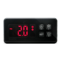
4- Front Panel Functions
LED Defrost (Controllers function).
Permanent: Indicates defrost in operation.
LED ºC
Permanent: Degrees ºC indicator.
Flashing: Programming phase.
LED ºF
Permanent: Degrees ºF indicator.
Flashing: Programming phase.
UP KEY
- In programming, it makes the displayed value increase.
- When pressed for at least 5 seconds, a manual defrost is started with programmed duration.
(Controllers function).
DOWN KEY
- In programming, it makes the displayed value reduce.
- When pressed for at least 5 seconds, the SP Set Point temperature is displayed. (Controllers
function).
LED Compressor
(Controllers function).
Permanent: Relay (compressor) energised
if control operates in cold.
Flashing: Because of the temperature
detected by Sensor, the Compressor relay
should be energised, but is no due to a
programmed parameter.
LED Heat
(Controllers function).
Permanent: Relay energised if control operates in heat.
Flashing: Because of the temperature detected by Sensor, the relay should be energised,
It should only be programmed or modified by personnel who are fully conversant with the
equipment operation and possibilities.
5- Adjustment and Configuration
5.1 Set point temperature
The factory SET POINT default value is 0.0 ºC.
- Press
key for at least 5 seconds to DISPLAY SET POINT. It displays the CURRENT SET
POINT value and LED ºC or ºF starts flashing.
- Press
or keys to CHANGE SET POINT into the required value.
- Pressing
+ keys simultaneously to ACCEPT THE NEW SET POINT. The display returns
to the CURRENT TEMPERATURE display status and LED ºC or ºF stops flashing.
When PA is displayed, PASSWORD programmed in L5 parameter of tid menu should be
entered to access the CURRENT SET POINT.
- Press
+ keys simultaneously. 0 will be displayed to ENTER PASSWORD.
- Press
or keys to CHANGE NUMBER and DISPLAY PASSWORD programmed.
- Press
+ keys simultaneously to ACCEPT PASSWORD. The CURRENT SET POINT value
will be displayed and it can be already modified.
Level 1 Menus
- Press simultaneously
+ keys for at least 10 seconds. LED ºC or ºF will be flashing,
we are in the programming LEVEL 1 MENUS and the first menu rE is displayed.
- Press
key to access the next menu and key to return to previous one.
- Pressing
+ keys simultaneously in the last parameter EP, the controller returns to the
CURRENT TEMPERATURE display status and LED ºC or ºF will stop flashing.
When PA is displayed, PASSWORD programmed in L5 of tid menu should be entered to
access programming LEVEL 1 MENUS.
- Press
+ keys simultaneously. 0 will be displayed to ENTER PASSWORD.
- Press or keys to CHANGE NUMBER and DISPLAY PASSWORD programmed.
- Press
+ keys simultaneously to ACCEPT PASSWORD. The first menu rE will be
displayed.
5.2 Parameters configuration
Level 2 Parameters
- In the desired menu of LEVEL 1 MENUS, press + keys simultaneously. LEVEL 2
PARAMETERS programming is accessed. The first parameter of the selected menu is displayed
on the screen.
- Press
key to access the next parameter and key to return to the previous one.
- Pressing
+ keys simultaneously in the last parameter EP, the controller returns to the
LEVEL 1 MENUS.
Level 3 Values
- To DISPLAY the CURRENT VALUE of any parameter, select the required one and press
+
keys simultaneously. Once it is displayed, you can CHANGE VALUE, pressing or key.
- Press
+ keys simultaneously to ACCEPT THE NEW. The programming returns to LEVEL
2 PARAMETERS.
1412H302 Ed.01
AKO-14012
AKO-14023
AKO-14112
AKO-14120
AKO-14123
AKO-14125
AKO-14129
AKO-14139
Thermometer
Thermometer
Controller
Controller
Controller
Controller
Controller
Controller
MODEL FUNCTION
RELAY 250 V, cos
j=1
POWER SUPPLY, 50/60 Hz
GB
LED HEAT
UP KEY
DOWN KEY
PRG
SET
ºF
LED ºC
ºC
LED ºF
LED COMPRESSOR
LED DEFROST
5 sec.
CURRENT
TEMPERATURE
ACCEPT
PASSWORD
DISPLAY SET
POINT
CHANGE SET
POINT
ACCEPT
THE NEW
ENTER
PASSWORD
DISPLAY
PASSWORD
CURRENT SET
POINT
NEW SET
POINT
IF P2 = 0 ó L5=0
PASSWORD
REQUEST
CHANGE
NUMBER
SIMULTANEOUSLY SIMULTANEOUSLY SIMULTANEOUSLY
3
2
1
m
a
x.
18 mm
61,5
44
PANEL CUT-OUT
28,5
70,5
we make it easy
-
-
16 A (13 (4) A s/EN-60730-1), SPDT
16 A (13 (4) A s/EN-60730-1), SPDT
16 A (13 (4) A s/EN-60730-1), SPDT
16 A (13 (4) A s/EN-60730-1), SPDT
30 A (18 (5) A s/EN-60730-1), SPST
30 A (18 (5) A s/EN-60730-1), SPST
12/24 V~/= ±20%
230 V~ ±10%
12/24 V~/= ±20%
120 V~ +8% / -12%
230 V~ ±10%
230 V~ ±10%
230 V~ ±10%
120 V~ +8% / -12%
121176
AKO-14012
AKO-14023
SONDA
PROBE
POWER SUPPLY
121187
AKO-14112
SONDA
PROBE
321
NCCNO
13 A
121154
AKO-14120
AKO-14123
AKO-14125
SONDA
PROBE
321
NCCNO
13 A
121154
AKO-14129
AKO-14139
SONDA
PROBE
21
CNO
18 A
POWER SUPPLY
POWER SUPPLYPOWER SUPPLY
54 8
AKO-14012AKO-14023
6