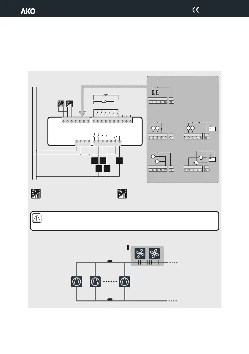
Control of fan inverter
S1: Aspiration probe
S2: Discharge probe
Control of compressor inverter
Probes S1 and S2 must be the same type (NTC, 4-20 mA or 0-5 V). They will be active depending on the INI value
selected.
Make the connection before plugging in the terminals to the equipment (see section 10.2).
5.- Wiring
The function of each relay output or digital input depends on the option chosen in the INI wizard (See page 5).
Location of the probes
15
12
16
13
17
14
18 19 20 21 22 23 24 25 26 27 28
I max.:
16 A
L N
I1
I2
I3
I4
I5
I6
Modbus*
Tr+
IN 1
S1
S3 (F08=1)
S3 (F08=1)
S1
I
I
S2
S2
NTC
IN 2
+15 V
+5 V
GND
Gnd
Tr-
0-10 V (³ 5KW) /
4-20 mA (£ 500W)
(C10)
S1
I
I
S2
4-20 mA
GND
+
+
+
4
1
5
2
6
3
7 8 9 10
11
AKO-14545
AKO-14545-C
R5
R1
R2
R3
R4
R1 R3
R2 R4
R5
S1
S1
0-5 V
S2
S2
IN 1
IN 1
IN 1
IN 2
IN 2
IN 2
+15 V
+15 V
+15 V
+5 V
+5 V
+5 V
GND
GND
GND
IN 1
IN 2
+15 V
+5 V
GND
V
V
V
V
+
+
+
+
+
-
-
90-240 V~
50/60 Hz
S2
S3
S1
9
1454H502 Ed.03
 Loading...