Page 9
The DeckMaster comes tted with a harness and connector ready for direct plug-in to the Universal II controller. While
this is congured for “plug and play” installation, removal of the connector to run through a bulkhead may be necessary
from time to time. In that event, or in the event of troubleshooting, the following table is provided for reference.
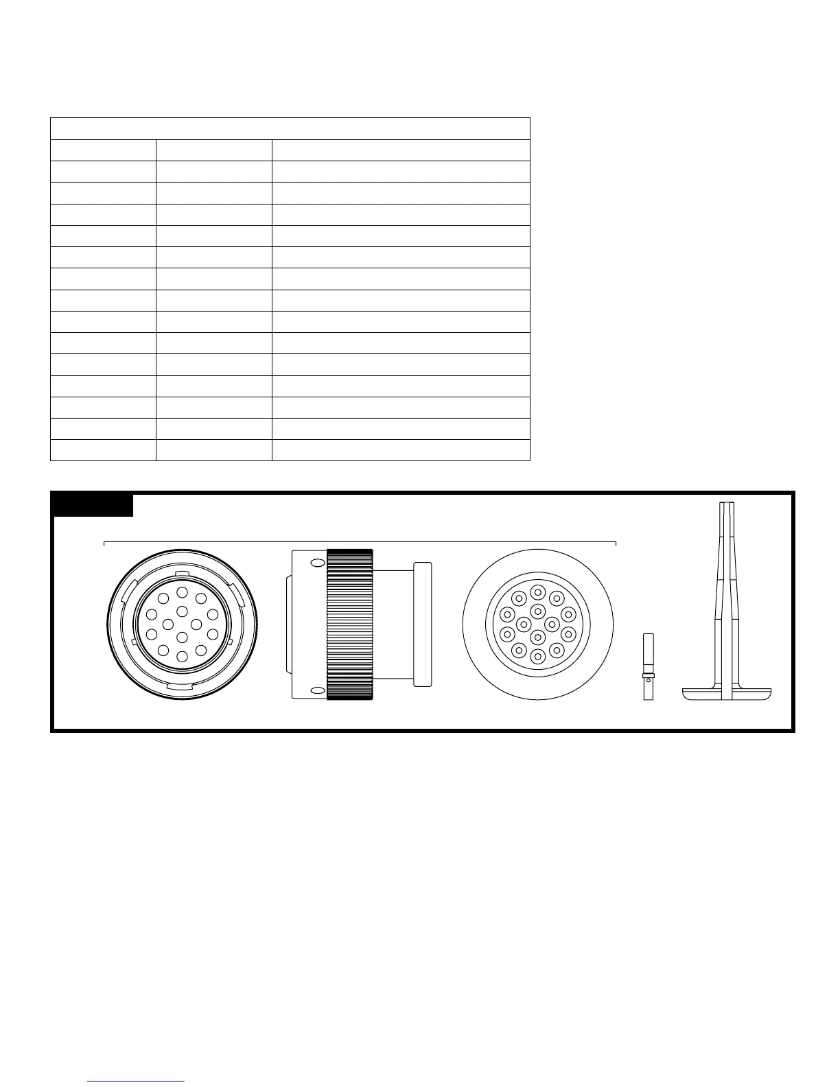
Deutsch Plug for J2 Connector on Controller (Part No. HDP26-18-14SN-L017)
Contact Position Wire Color Function
A Black Power Out – Switch and Position Sensor (−)
B White Input – Rotation Switch (Voltage)
C (Sealing Plug) Input – Multifunction #2 (Unused)
D Red Input – Swing Arm Position Sensor (Voltage)
E Green Power Out – Position Sensor (+5 VDC)
F (Sealing Plug) Data – Lin Bus (Unused)
G Orange Output – Rotation Motor (Right)
H Blue Output – Rotation Motor (Left)
J White/Black Output – Elevation Motor (Up)
K Red/Black Output – Elevation Motor (Down)
L Green/Black Output – Pattern Motor (Stream)
M Orange/Black Output – Pattern Motor (Fog)
N Blue/Black Output – Swing Arm Motor (Deploy)
P Black/White Output – Swing Arm Motor (Stow)
Table 2 – Monitor Harness Connections
3440 DeckMaster with UII control Initial setup
The following functions can be congured in the setup mode:
• Monitor Orientation (sideways or inverted mounting)
• Restore Factory Defaults
• Obstacle Avoidance
• Electric Riser Disable/Enable
• Stow and Deploy Positions
To enter the setup mode, follow these steps:
1. Turn power off to the Universal II Controller.
2. Press and HOLD the Stream switch (can be done on the Joystick or the Toggle Switch Box).
3. Turn power on to the Universal II Controller while continuing to hold the Stream switch.
4. Wait 3-4 seconds and release the Stream switch.
The Universal II Controller should now be in setup mode. When in setup mode, the LED on the operator station will
be slowly blinking (a short blink followed by a long pause). If it is not slowly blinking, repeat steps 1-4 above.
FIGURE: 5
FRONT VIEW
F
G
H
J
K
A
B
C
D
E
L
M
N
P
SIDE VIEW REAR VIEW
M
L
K
J
H
C
B
A
D
N
G
F
E
P
DEUTSCH
HDP 26-18-14SN-L017
DEUTSCH
0411 -310-1605
CONTACT
REMOVAL TOOL
DEUTSCH
0462 -201-16141
SOCKET
CONTACT