Do you have a question about the Alamo John Deere 6615 and is the answer not in the manual?
Emphasizes reading safety messages and observing rules before operating the equipment.
Explains the Safety Alert Symbol and Signal Words (Caution, Warning, Danger) and their associated decal colors.
Provides essential safety messages for operation, service, and handling of equipment.
Details required PPE like hard hats, safety shoes, glasses, and safe welding practices.
Covers safe operating procedures, SMV signs, tractor starting, and hydraulic oil handling precautions.
Warns against impaired operation, hot surfaces, and chemical exposure risks.
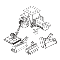
Lists recommended tools, supplies, and equipment necessary to complete the assembly process.
Details checks for safety equipment, frame, boom, hydraulic system, and rotary mower head before operation.
Covers inspection points for the Flail Mower Head and the tractor's operation during a 30-minute test run.
Provides instructions for filling the left rear wheel with a calcium chloride water mixture for added weight.
Details the procedure for installing the 1400 lb wheel weight using bolts and special washers.
Covers the installation of pump drive components, pump assembly, and the hydraulic tank.
Details the steps for accessing the crankshaft pulley and installing the pulley adapter and driveshaft assembly.
Explains how to install the pump mount plate and connect the tube end of the driveshaft.
Guides on installing the pump into the splined clamp yoke and adjusting the gap.
Details the process of removing existing bolts and installing the front frame rail supports on both sides.
Describes the process of setting up frame rails, tack welding, and disassembling for final welding.
Explains how to identify and mount the right and left frame rails, noting differences in counter weight tubes.
Details the installation of the frame rail stiffener kit, including crossmembers and support gussets.
Covers the components used for mounting the high frame, including tubes and straps.
Explains the sub-assembly of the high frame and king post, noting differences between 2 WD and 4 WD models.
Provides instructions for laying out components and installing front frame rail supports and gusset mounts.
Details mounting the front rail pad and preparing the tractor axle housing by removing plastic plugs.
Guides on lifting and installing frame rails, and bolting together the frame stabilizer kit.
Explains how to raise the stabilizer kit, align it with the gusset support, and align frame rails on front mount pads.
Covers unbolting the high frame from its pallet and preparing it for lifting using lift lugs.
Details lowering the high frame over the tractor and using magnetic levels to ensure it is properly positioned.
Guides on aligning the high frame's vertical tube with the frame rails and clamping for alignment.
Instructions for loosely bolting mounting tubes to the frame rails and aligning them.
Details installing the front angle mount on the mounting tubes, including the use of a washer for gap adjustment.
Provides instructions for tack welding frame rails to mounting pads and stiffeners, avoiding the stabilizer gusset.
Explains the frame stiffener assembly and locating mounting tubes and hardware for the high frame.
Details tack welding angle mounts to frame rails and mounting tubes to the high frame.
Guides on welding bar mounting straps to the mounting tubes and frame rails, ensuring proper alignment.
Instructs on removing the high frame and fully welding the mounting tubes for strength and quality.
Details welding the front mount plate and front/rear angle mounts to the frame rails.
Covers welding the side rails to support plates and attaching pigtail brackets for hose support.
Guides on re-installing the frame rails to the tractor, including mounting to the rear axle housing and front plates.
Details the installation of the axle mounted boom rest, requiring two people for alignment.
Covers installing the stabilizer crossmember and welding the stabilizer gusset to the rail stiffener.
Guides on preparing the high frame's paint, mounting it to the tractor, and aligning mounting holes.
Details installing mounting tube bolts and bar mounting straps, ensuring proper alignment and snugging.
Instructs on tightening all frame mounting bolts, including front mounting pads, stiffener crossmember, and rear axle connections.
Shows the final assembled high frame and guides on tying down hoses and cables to the tractor frame rail.
Provides instructions for installing the hydraulic tank on the LH side of the frame rail, ensuring cleanliness.
Details mounting the counter weight and its cover to the LH side of the hydraulic tank.
Covers installing the oil level sight gauge and applying various decals to the hydraulic tank and CWT cover.
Guides on installing decals on the tractor's cab windows and interior, ensuring proper placement and visibility.
Instructs on installing the cutter motor control valve assembly onto the LH side of the high frame.
Details pulling out the lift cylinder, attaching hoses, and lowering the boom arm onto the king post.
Guides on attaching the lift cylinder rod end and connecting the swing cylinder to the king post and high frame.
Provides instructions for connecting the suction hose from the tank to the pump and pressure hoses to the control valves.
Details connecting hoses from the pump to cylinders, cutter valve to motor, and return hoses to the tank and filter.
Guides on bolting control handles, the ON/OFF switch, and arm rest, and routing cables through the floor.
Illustrates the wiring diagram for connecting the ON/OFF switch to the tractor ignition and solenoid cutter valve.
Explains wire harness connections and common issues like tractor not starting or cutter motor not working.
Describes the standard 4-spool and 5-spool control valves and their operation, excluding optional joystick controls.
Details the single pump system option and how the control valve bolts onto the high frame.
Presents the hydraulic schematic and control circuit for the 4-spool and 5-spool valve systems.
Explains hydraulic power sources, cylinder operation, pressure relief valves, and valve spool functions.
Details hose identification for hydraulic cylinders and lists connections for mechanical valve models.
Guides on using cables and remote actuator handles for boom movement control and installing cable kits.
Illustrates the components for cable assembly, including flange, sleeve, washers, and cable eye fittings.
Provides step-by-step instructions for turning the cable eye jam nut, sliding the cable eye, and tightening the flange.
Details installing controller assemblies, attaching cables, and checking spool, cable, and controller operation.
Lists the components required for mounting the joystick assembly to the tractor seat.
Guides on removing the seat cushion, mounting the joystick bracket, and re-installing the seat cushion.
Details bolting the joystick to the bracket and preparing the tractor floor mat for wire harness routing.
Guides on routing the wire harness through the cab floor plug and connecting the necessary wires to tractor circuits.
Explains connecting the ground wire and installing the wiring harness to the joystick connection.
Provides instructions for cleaning windows and identifying, then installing, various warning and instruction decals.
Guides on routing the wire harness from the cab to the front and preparing for valve terminal connections.
Details identifying and installing wire harness terminal plugs onto the valve, ensuring correct order and gasket use.
Guides on connecting the solenoid lock valve and notes regarding the servo control manifold solenoid.
Illustrates the wiring schematic for the joystick plug, showing master switch, rocker switches, and motor relay connections.
Shows the wiring schematic from the joystick console plug to the valve, detailing pin locations and connections.
Introduces the Electro-Hydraulic control valve, its compatibility, and hydraulic supply source.
Illustrates the 5-spool control valve and shows the starter solenoid and junction box connections.
Guides on attaching the boom weldment to the flail axe head, aligning the hitch post, and installing hoses.
Details attaching the boom weldment to the flail head, aligning the hitch post, and connecting hoses.
Provides instructions for attaching the boom weldment to the ditcher head, aligning the hitch post, and connecting hydraulic hoses.
Guides on attaching the timber cat head to the boom, connecting hoses, and performing initial checks.
Details attaching the boom weldment to the X-Frame square head and connecting hoses to the mower.
Provides crucial instructions on filling the hydraulic tank with oil, emphasizing cleanliness and avoiding contamination.
Guides on filling the hydraulic tank to the sight gauge level and filling the suction hose to prevent pump dry start.
Covers reading safety instructions, filling the tank, starting the tractor, bleeding cylinders, and running the mower.
Provides troubleshooting tips for common initial start-up issues like electrical problems, pump noise, and cylinder movement.
A comprehensive checklist of items to verify after assembly, including oil levels, hose tightness, decals, and head operation.
Guides on mounting the boom rest plate and hook, swinging the boom, and measuring for stop plate welding.
Details marking the boom for alignment and clamping the boom rest hook before welding.
Provides instructions for positioning, tack welding, and fully welding the boom swing stop lug to prevent cab collision.
| Brand | Alamo |
|---|---|
| Model | John Deere 6615 |
| Category | Lawn and Garden Equipment |
| Language | English |