SOLID DOOR
ALARM CONTROLS CORPORATION
19 BRANDYWINE DRIVE P.O. BOX 280
DEER PARK, NY 11729
800 645-5538 WWW.ALARMCONTROLS.COM
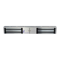
MAGNETIC LOCK INSTALLATION INSTRUCTIONS
ALARM CONTROLS CORPORATION OFFERS A COMPLETE LINE OF MAGNETIC LOCKS AND ACCESSORY ITEMS
TO ASSIST THE INSTALLER IN MANAGING EVERY APPLICATION.
THE MAGNETIC LOCK IS DESIGNED TO MOUNT TO THE DOOR FRAME ON THE STOP SIDE OF THE DOOR IN A
TYPICAL OUTSWINGING DOOR INSTALLATION,(SEE PAGE 2 FOR INSWINGING DOOR INSTALLATION).
SUFFICIENT HEADER SPACE MUST BE AVAILABLE TO MOUNT THE MAGNETIC LOCK TO INSURE A SAFE AND
SECURE INSTALLATION.
1. NOTE TYPE OF DOOR FRAME HEADER AND INSTALL FILLER PLATE OR ANGLE BRACKET AS REQUIRED TO
PROVIDE A FLAT MOUNTING SURFACE ON THE DOOR HEADER THE ENTIRE LENGTH OF THE MAGNETIC LOCK.
HEADER
HEADER HEADER
OUT
SWINGING
DOOR
OUT
SWINGING
DOOR
OUT
SWINGING
DOOR
MAGNET
MAGNET
FILLER
PLATE
MAGNET
ARMATURE
PLATE
ARMATURE
PLATE
ARMATURE
PLATE
ANGLE
BRACKET
HEADER
PLATE
2. FOLD TEMPLATE ON DOTTED LINE TO FORM A 90 DEGREE ANGLE. TAPE TEMPLATE AGAINST DOOR HEADER
WITH DOOR IN A CLOSED POSITION 1” FROM DOOR FRAME OPPOSITE HINGE SIDE OF DOOR JAMB.
FOR A PAIR OF DOUBLE DOORS PLACE TEMPLATE AT THE CENTER OF THE DOOR OPENING.
TRANSFER HOLE LOCATIONS TO DOOR AND FRAME HEADER, (SEE TEMPLATE INSTRUCTIONS).
3. FOLLOW TEMPLATE INSTRUCTIONS FOR HOLE SIZES. USE THE ILLUSTRATIONS BELOW TO DETERMINE THE
PROPER HOLE PREPARATION FOR THE ARMATURE PLATE ACCCORDING TO THE DOOR TYPE IN THE
INSTALLATION.
THE INCLUDED HARDWARE PACKAGE CONTAINS ALL NECESSARY ITEMS TO COMPLETE THE INSTALLATION.
HOLLOW DOOR
STEP 2
FOLLOW WITH
1/2” DIA. HOLE
THRU DOOR
STEP 1
DRILL 1/4” DIA.
HOLE THRU
ARMATURE
SIDE OF DOOR
STEP 2
DRILL 1/2” DIA.
HOLE THRU SEX
BOLT SIDE
OF DOOR
ONE THICKNESS
ONLY
STEP 1
DRILL 21/32” DIA.
HOLE THRU
ARMATURE
SIDE OF DOOR
ONE THICKNESS
ONLY
OUTSWINGING DOOR INSTALLATION
ARMATURE
PLATE MUST
ROCK ON DOOR
ARMATURE
PLATE MUST
ROCK ON DOOR
PLEASE READ BEFORE INSTALLATION
TO REMOVE THE HEADER PLATE INSERT HEX KEY INTO HOLES LOCATED AT
THE BOTTOM OF LOCK ON THE RIGHT AND LEFT SIDE AND UN-SCREW THE CAP SCREWS