Do you have a question about the Alcatel OmniSwitch 8800 and is the answer not in the manual?
Lists the products to which the information in this guide applies.
Identifies the target audience for this user's guide.
Details the hardware-related information covered in the user's guide.
Outlines the documentation suite for switch configuration stages.
Information on obtaining technical support, software updates, and service programs.
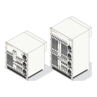
Illustrates a typical enterprise network setup using OmniSwitch 8800 switches.
Describes hardware and software safeguards to prevent data flow loss.
Explains backup hardware components and their role in failover.
Details the process of adding or replacing components without powering off the switch.
Covers automatic monitoring via sensors and user-driven monitoring via CLI.
Provides detailed technical specifications for the OmniSwitch 8800 chassis.
Instructions for installing the switch in a rack or as a stand-alone unit.
Step-by-step guide for securing the chassis in a standard rack.
Details AC and DC power supplies, their front panels, and specifications.
Explains N+1 power supply redundancy for continuous operation.
Procedure for physically installing a power supply into the chassis bay.
Guidelines for maintaining optimal operating temperatures to prevent failure.
Information on front and back fan trays for chassis cooling.
Details MAC address ranges, allocation, and guidelines for the switch.
Identifies the physical slots for installing CMM modules in the chassis.
Describes the LEDs, ports, and connectors on the CMM front panel.
Explains the importance and setup of redundant CMM configurations.
Illustrates the sequence of events during a primary CMM failure.
Details the procedure for removing or replacing a CMM while the switch is operating.
Covers reloading CMMs and switching primary/secondary roles.
Instructions for performing a soft boot of a CMM module.
Procedure to manually designate the secondary CMM to assume the primary role.
Methods for accessing CMM hardware and operating status information.
Identifies the rear chassis slots where SFM modules are installed.
Describes the LEDs and technical specifications of the SFM front panel.
Explains how a fifth SFM provides redundancy for the switch fabric.
Illustrates the failover process when a primary SFM fails.
Procedures for grounding, adding, and removing SFM modules.
Commands to control the power state of SFM modules (on, off, standby).
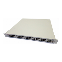
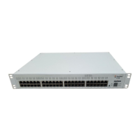
Details Ethernet Network Interface modules and their features.
Describes the front panel layout, LEDs, and ports of the OS8-ENI-C24 module.
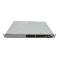
Details Gigabit Ethernet Interface modules and their types.
Technical specifications for MINIGBIC-SX, LX, and LH-70 types.
Procedure for installing Miniature Gigabit Interface Converters into GNI modules.
Details 10 Gigabit Ethernet Interface modules and their specifications.
Explains port redundancy and configuration for the OS8-10GNI-UR1 module.
Technical specifications for OM-10GNI-SR, LR, and ER Xenpak types.
Describes how NI modules maintain data flow during CMM failover.
Covers powering modules on/off and individual module reloads.
Details the process of removing or replacing NI modules without downtime.
Lists safety and EMC standards the product complies with.
Provides safety warnings in multiple languages for user guidance.
Emphasizes the need for two people to lift the chassis safely.
Warns about explosion risk from incorrect Lithium battery replacement.
Advises keeping hands away from power supply bays to prevent shock.
Instructs to disconnect all power before servicing or moving the unit.
Stresses the need for properly wired and earthed power connections.
Highlights the importance of grounding oneself to prevent ESD damage.