EasyManua.ls Logo

Alcor EGT Probe User Manual

Alcor EGT Probe
4 pages
To Next Page IconTo Next Page
Page #1 background imageLoading...
Page #1 background image
Take a Flight
to Our Web Site
Web site: www.alcorinc.com
E-Mail: support@alcorinc.com
PN 59180
REV. G, 01/08
FAA-PMA/STC SA 522
SW: This product is FAA
approved for installation
on ALL piston engine
aircraft. After installation
of complete system,
return aircraft to service
via Form 337 referenc-
ing STC SA 522 SW.
This is not required for
replacement parts. All
piston powered aircraft,
regardless of make, are
covered by this STC.
– 4
EGT Probe
Installation Instructions
FAA/PMA Approved
WARRANTY INFORMATION
www.alcorinc.com
Alcor
©
, Inc. warrants all parts in all new Alcor
©
, Inc. products to be
free from defects in material and workmanship under normal use and under
the following conditions: Alcor
©
, Inc.’s obligation under this warranty is limited
to the repair or exchange of any defective part, if the part is returned and return
shipping prepaid, within FIVE YEARS of the date of manufacture for grounded
thermocouples and within ONE YEAR of the date of manufacture for
ungrounded thermocouples.
Alcor
©
, Inc. is not responsible for any service charges, including removal and
reinstallation costs, or any other consequential damages. This warranty is
void as to any product damaged as a result of misuse, accident, negligence,
unauthorized repairs or handling in transit. If the Alcor
©
, Inc. product's serial
number or inspection date label has been altered, the warranty is void.
Questions concerning all Alcor
©
, Inc.’s products should be directed
to Customer Support at 1-800-FLI-SAFE (1-800-354-7233) or email:
support@alcorinc.com.
Question and Answer IconNeed help?

Do you have a question about the Alcor EGT Probe and is the answer not in the manual?

Alcor EGT Probe Specifications

General IconGeneral
BrandAlcor
ModelEGT Probe
CategoryMeasuring Instruments
LanguageEnglish

Summary

General Information on EGT Probe Installation

Clamp Type EGT Probe Installation

Drilling and Hole Preparation

Drill and ream hole for clamp type probe, ensuring correct size for press fit.

Clamp and Probe Placement

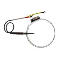
Place clamp around exhaust pipe and tighten to remove looseness.

Seating and Securing the Probe

Seat probe shoulder to exhaust pipe, torque clamp, and consider safety wiring.

Lead Connection and Slack

Install insulation sleeve, connect leads, and allow slack for strain relief.

Screw-In Type EGT Probe Installation

Weld Boss and Probe Insertion

Drill hole, insert probe into weld boss, tack weld, remove probe, and weld boss.

Drilling and Thread Protection

Drill a .125 inch hole through exhaust pipe center of boss.

Probe Securing and Tightening

Insert element up to .75 inch and tighten probe nut securely.

Probe Installation Best Practices

Incorrect Probe Positioning

Illustrates incorrect probe installation angles and insufficient hole size.

Correct Probe Positioning

Shows ideal probe location for minimum interference with a welded seam.

Troubleshooting and Testing

Cylinder Selection for New Probes

Install probe on the cylinder that peaks first while leaning for accurate EGT readings.

Meter Not Responding

Verify probe type, check lead resistance, and consider meter calibration issues.

Testing Without Expensive Equipment

Test probe by measuring loop resistance and checking for wire breaks.

Resistance and Weight Specifications

Warranty Information

FAA Supplemental Type Certificate

Related product manuals