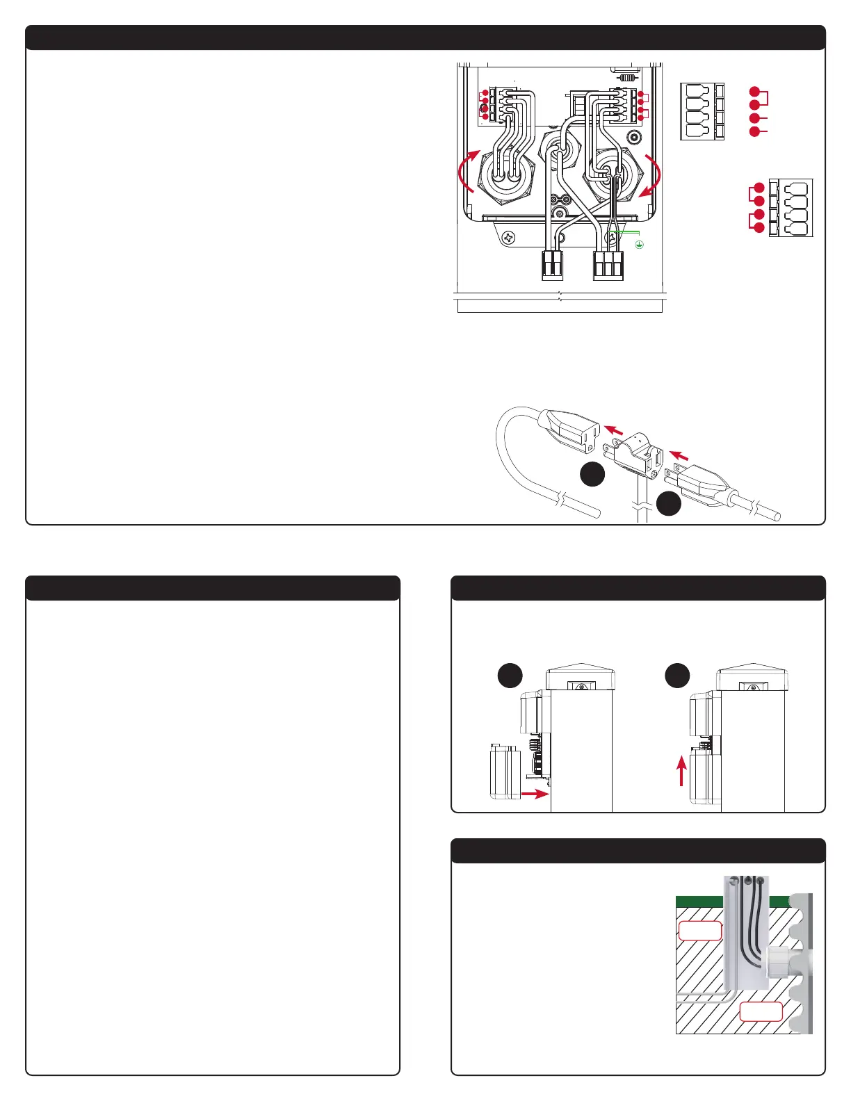
Step 5: Wiring and Piggyback Plug Connections
Step 6: Testing
The wiring diagram shows eight terminals on the quick snap terminal
blocks that consists of four pairs of connections. Make sure to read and
review the connector examples in step 4 for proper installation prior to
wiring.
Note: The quick snap terminal blocks, are herein referred to as “terminal”
for instruction purposes. The installation example shown is for 120VAC,
for 240VAC installation the neutral (N) wire would be replaced by line
connection (L2) and white wire would include a red band to indicate the
wire is hot.
1) The rst cable grip, starting at the right, has a cable grip divider
allowing for two power sources to be brought into the enclosure. The
right side of the cable grip is used for the pump power (attached in
series). The line wire is connected to terminal 7 and neutral wire is
terminated by the two-position Wago connector. The left side of the
cable grip is used for the alarm power, which is connected to
terminals 5 and 6. Terminal 5 is the neutral (N) connection and
terminal 6 is the line connection (L1). The pump and alarm power
ground wires are terminated using the three-position Wago
connector. After bringing in the cables, rmly tighten the cable grip
by twisting clockwise until securely fastened.
2) The female receptacle comes pre-installed in the middle cable grip.
The line wire is connected to terminal 8, neutral wire is terminated by
the two-position Wago connector, and ground wire is terminated by
the three-position Wago connector.
3) The third cable grip has a cable grip divider allowing for two sensor
connections. The lter switch is connected to terminals 1 and 2. The
high level alarm oat switch is connected to terminals 3 and 4. After
bringing in the cables, rmly tighten the cable grip by twisting
clockwise until securely fastened.
4) NEVER leave ground wire(s) exposed, use provided Wago
connector for wire termination.
(120VAC Example Shown)
5B
5A
PIGGYBACK PLUG CONNECTIONS
1) Plug the male end of the piggyback plug on the pump switch power
cable into the pre-installed female power receptacle inside the post (5A).
2) Plug the male end of the pump power cable into the female end of
the piggyback plug on the pump switch power cable (5B) from #1.
Alarm Wiring
(step 3)
Filter Switch
Alarm Float Switch
1
2
3
4
Make sure all steps of the installation and wiring process is completed
and there is power to the product.
1) TEST ALARM LEDs and BUZZER
Press the test/silence pushbutton, lifetime pump run event counter
statistic should display, then alarm LEDs should illuminate while
cycling between red, green, blue, and off. The OLED screen should
display a TESTING (COLOR) event for respective LEDs after the event
statistic is displayed. Last, the buzzer should annunciate and OLED
screen should display a TESTING BUZZER event.
2) TEST ALARM FLOAT SWITCH
Activate the alarm oat switch, the red LEDs should illuminate,
ashing and the buzzer should annunciate. The OLED screen should
display a HIGH LEVEL ALARM event.
3) TEST ALARM SILENCE
Press the test/silence pushbutton on the front of the enclosure while
the alarm oat switch is activated. The red LEDs should keep ashing
and the buzzer should silence.
4) TEST FILTER SWITCH
Activate the lter switch, the amber LEDs should illuminate, ashing
and the buzzer should annunciate. The OLED screen should display a
FILTER ALARM event.
5) TEST PUMP AND PUMP FLOAT SWITCH
Make sure the tank has water to perform the testing. Activate the pump
oat switch, the blue LEDs should illuminate and the OLED screen
should display a PUMP RUN event and the pump amps are displayed.
6) RECOMMENDED SYSTEM SETTINGS
Alderon™ recommends changing the factory settings for: high amp
level, extended pump run time, and gallons per minute.
7) TEST WEEKLY
To ensure the product is functioning properly, test once a week.
Step 7: Install Bottom Cover
Line up the bottom enclosure cover with the grooves (7A), then slide
directly upward (7B) until it meets the top of the enclosure so the screw
hole is lined up and replace the screw at the bottom of enclosure.
Step 8: Backll
Make sure all steps of the installation,
wiring, and testing are complete. Take
the dirt/soil removed and backll the
area for the post, riser, and direct
burial power wiring.
Backll
Area
Backll
Area
7A 7B
BLACK
BLACK
BLACK
BLACK
WAGO WAGO
GROUND
WHITE/RED
WHITE
WHITE/RED
WHITE
BLACK
WHITE
GROUND
5
6
7
8
1
2
3
4
Power Wiring
(steps 1 and 2)
Alarm Power
Pump Power
5
6
7
8
Factory Wired
N/L2
L1
L1
 Loading...