2
1. AIRFLOW SETTING
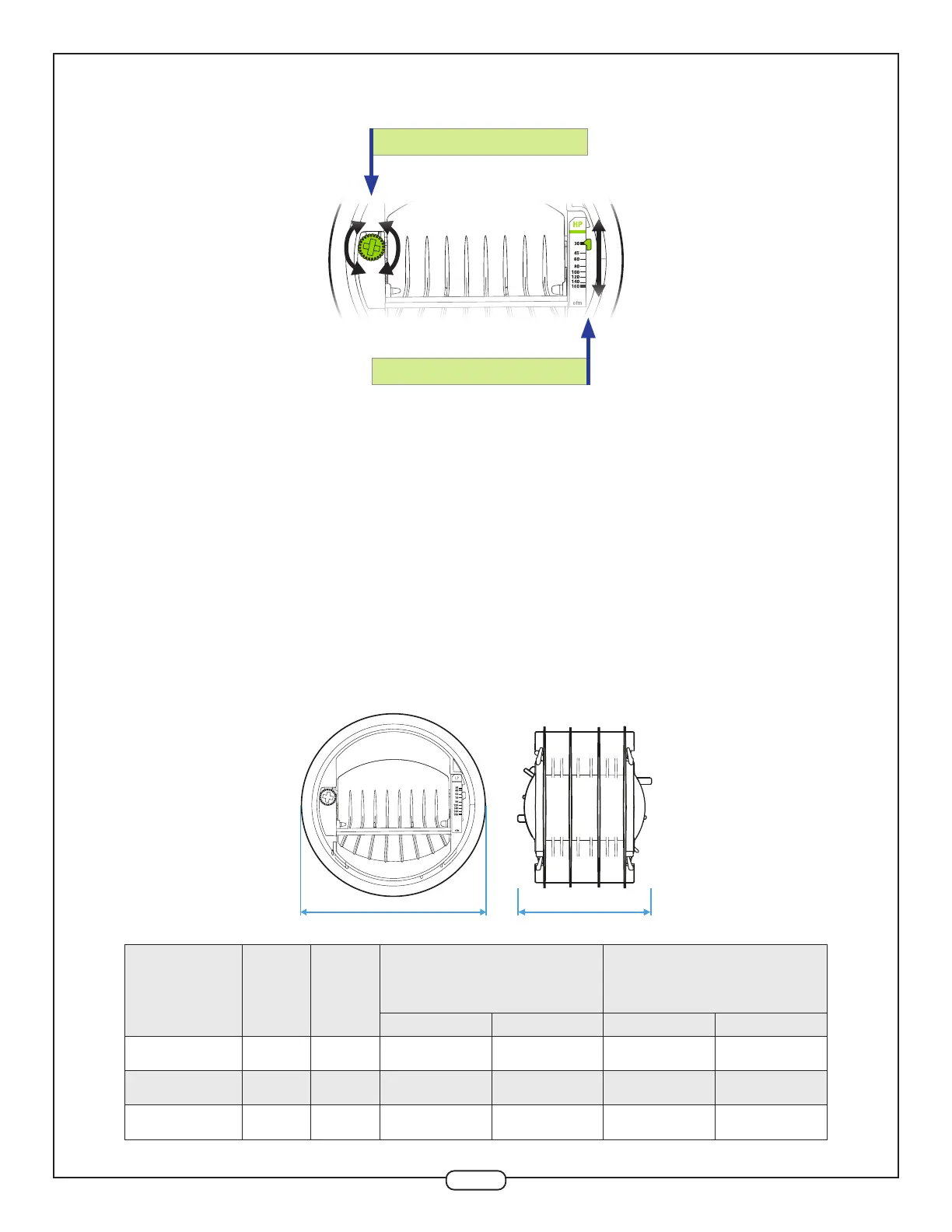
Airow rate can be set or adjusted by rotating the dial from either side. The airow indicator will move
to show the selected CFM. The airow label has multiple dened setpoints, but the unique adjustment
mechanism of the CAR3 allows for innite adjustability between the minimum and maximum limits.
Performance charts found in the specications sheet reect this data, with the available range (shaded)
and marked setpoints (lines). The CAR3 will maintain the airow accurately to within +/- 10% of the
indicated lines below for each marked setpoint. At the higher airow rates, the minimum pressure
required to achieve the selected airow may exceed 0.12 in. w.g.
Each diameter has a unique range for both low- and high-pressure variants. The CAR3-L (low-pressure)
is designed for systems with pressures between 0.12 and 1.2 in. w.g. (30 to 300 Pa), and CAR3-H (high-
pressure) between 0.4 and 2.8 in. w.g. (100 to 700 Pa). Factory calibration of the CAR3 is available on
request. Blue color dial = Low-Pressure / Green color dial = High-Pressure.
ADJUSTMENT DIAL
AIRFLOW INDICATOR
2. DIMENSIONS
Ø B A
Size A Ø B
Low-Pressure (Blue)
0.12-1.2 in. w.g
(30-300 Pa)
High-Pressure (Green)
0.4-2.8 in. w.g
(100-700 Pa)
Airflow P/N Airflow P/N
4'' (100 mm) 3’’ 4.3’’ 15-85 CAR3L4R4 30-160 CAR3H4R4
5'' (125 mm) 3.8’’ 5.2’’ 35-180 CAR3L5R5 55-260 CAR3H5R5
6'' (150 mm) 4.6’ 6.0’’ 45-260 CAR3L6R6 60-370 CAR3H6R6