. .
11
WIRING CONNECTIONS
H2/4 BROWN Wire (Siren Output)(Factory Default setting)
The BROWN wire will provide a (+) positive output for the optional
siren. Also programmable for horn output (relay required).
H2/5 RED Wire (System +12volt Constant Power)
Connect the RED wire to a constant +12 volt source.
The RED wire supplies power to the system. Connect this wire to a
constant +12 volt source.
H3: BLACK 4-PIN CONNECTOR,
TWO-WAY TRANCEIVER/ANTENNA MODULE
The two-way transceiver/antenna mounts on the location above the belt
line (dashboard) of the vehicle for best reception. We suggest you mount
it on the lower left or upper left-hand side of windshield. Warning! Do not
mount in such a manner that it obstructs the drivers view.
Remove the protective tape backing.
Carefully align the two-way transceiver/antenna and apply to the
windshield.
Route the black connector wire behind the trim and connect to the
two-way transceiver/antenna.
Connect the other end to the control module.
Special considerations must be made for windshield glass as some newer
vehicles utilize a metallic shielded window glass that will inhibit or restrict
RF reception. In these vehicles, route the two way transceiver/antenna
module away from metallic shielded window glass as far as possible.
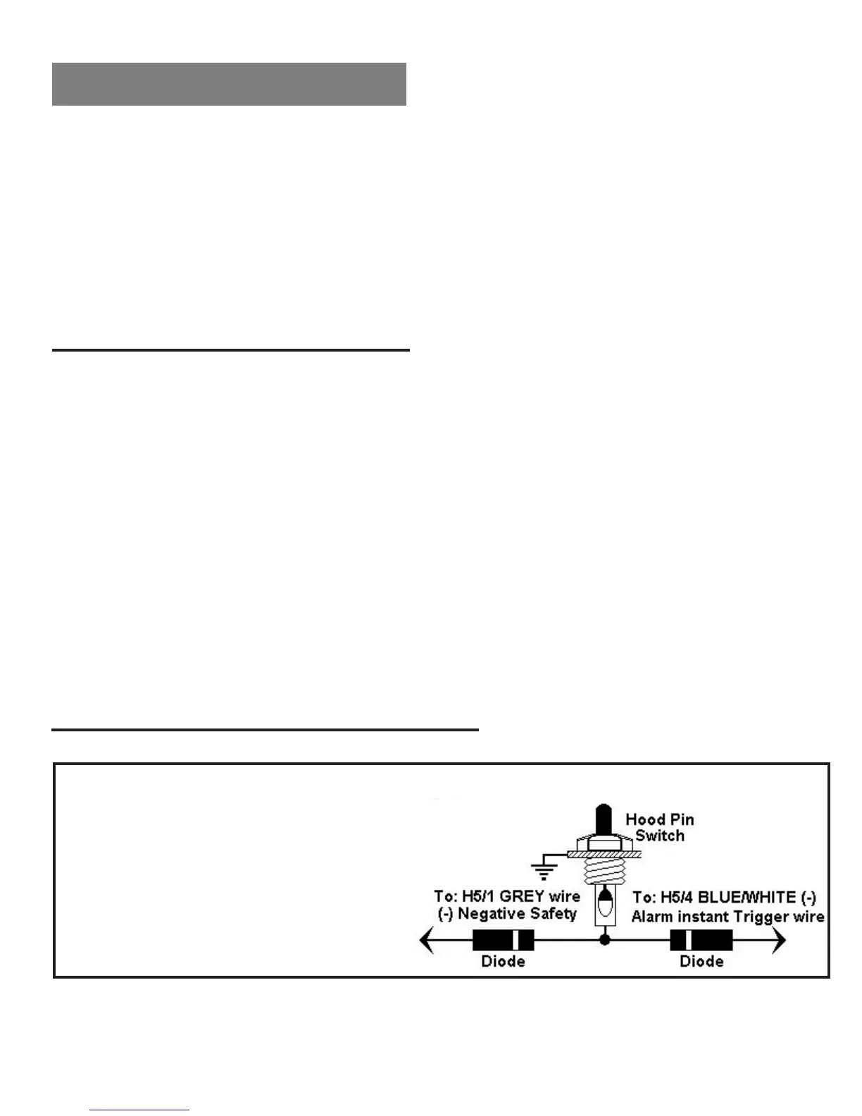
H5 9-PIN BLACK WIRING HARNESS:
This wire provides an instant shutdown for the remote start, whenever it
is grounded. Connect the wire to the hood pin
switch previously installed. This wire must
be routed though a grommet in the
firewall and connected to the hood
pin switch. If the pin switch is to
be used with an alarm system,
connect this wire with diode.
H5/1 GREY Wire (-) (Negative Safety Shut Down For Hood Switch)
 Loading...