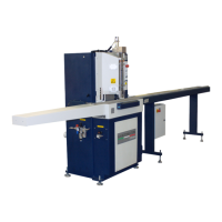
The Double Mitre Saw T-2300, T-2350, T-2400 is a specialized cropping machine designed for precise 45° cuts on wooden mouldings, hard plastic, and light alloys. It operates with vertical descent blades and is primarily intended for manual use under operator control. The machine is manufactured by ALFAautomation, a company with over 20 years of experience in double mitre saw construction, located at Via dell' Artigiano, 12 - 47121 Forlì - Italy.
Function Description
The core function of the Double Mitre Saw is to cut frames for pictures, furniture, windows, or looms with high precision. The blades descend vertically at a 45° angle, controlled by a pneumatic system. This system also incorporates a couple of pressors that clamp the mouldings securely onto the working bench during the cutting process. A pneumatic device facilitates a quick blade backstroke, optimizing efficiency and minimizing air consumption. The machine's design ensures that the blades move and rotate in specific directions for optimal cutting performance.
Important Technical Specifications
The Double Mitre Saw models T-2300, T-2350, and T-2400 share several key technical specifications:
- Working Principle: Vertical descent cropper with blades at 45 degrees.
- Main Components: Floor stand and working bench set, vertical descent blades set on the Z-axis, padlockable air filter lubricator set, pneumatic system, and electrical equipment.
- Dimensions: Overall dimensions are detailed in attachment 9.2-A.
- Length of right working bench extension: 1200mm
- Length of left working bench extension: 1200mm
- Working bench length: 800 mm
- Working bench height (from the floor): 950mm
- Motors: Two motors, each with 1.5 kW power.
- Max Revolutions per Minute: 2800 n/'.
- Pneumatic Feed: 5/7 bar.
- Power Consumption: 3 kW.
- Profiles Width (Min/Max): 15/60 mm.
- Profiles Height (Min/Max): 10/80 mm.
- Electric Power Supplying: 400V/230V, three-phase voltage 380 Volt +/- 10%, nominal frequency 50 Hz +/-2%. The feeding should not be interrupted or the voltage should not be zero for longer than 3 m/s. Voltage falls should not exceed 20% of peak voltage for more than one cycle.
- Suction Holes: 100 Mm.
- Total Weight: 380 Kg.
- Blades:
- A (Inner Diameter): 30mm
- B (Outer Diameter): 300mm
- Thickness: 2.50mm
- Customers can request different types of blades suitable for light alloy, wood, or plastic. For light alloy, the machine must be equipped with a Mist-Spray Cooling System.
Usage Features
The machine offers several features for ease of use and operational flexibility:
- Control Panel: Includes Run/Stop control (A), Main Switch (B), and Emergency Control (C). The Run/Stop control is located under the working bench, the Main Switch on the machine's right side, and the mushroom-headed Emergency button above the working bench on the right.
- Pneumatic System: Features a padlockable reducer-lubricator filter (B), a pressure regulator for pressor cylinders (C), and a flux adjuster (A) to control blade descent/ascent speed. The feeding pipe must have an internal section of at least 10 mm if the compressor is closer than 5 meters, and higher than 10 mm if the compressor is further away.
- Pressor Adjustment: Equipped with 4 vertical pressors functioning in couples (frontal and rear) to clamp mouldings. These can be activated individually or together via switches located under the main switch on the right side. The clamping cylinders can be horizontally adjusted, and their working pressure can be regulated.
- Rear Support Adjustment (T300/A version only): An adjustable rear mobile support helps reduce scrap by allowing precise positioning of mouldings.
- Rabbets Adjustment: Features a measurement gauge and two rabbets (one fixed, one tipping) for quick and exact moulding length dimensioning.
- Blades Adjustment:
- Cutting Angle Adjustment: Allows for fine-tuning the cutting angle. To enlarge, release nuts A1, A2, A3, nut E2, and screw D2 (quarter turn max), then fasten E2 and C1. To reduce, release A1, A2, A3, E2, and slightly release C1.
- Blades Positioning: Ensures an optimal room of 1.5-2.0 mm between the blades at the vertex.
- Blades Vertical Angle Adjustment: Adjusts the vertical angle by releasing nut A1 and screwing/unscrewing nut B1 (max 1/8 of turn).
- Safety Features: Equipped with adequate protections for mobile members (blades, pulleys, belts) and movable organs (blades, ejection of pieces/swarfs/dust). Stop functions include Main Switch (category 0), Normal Stop Button (category 1), and Emergency Button (category 1).
Maintenance Features
Regular maintenance is crucial for the machine's longevity and performance, with specific procedures outlined:
- General Maintenance: Operations must be performed by experienced staff. Before any maintenance or repair, the machine must be isolated from feeding sources by opening and padlocking the electric cut-out switch and the pneumatic cut-out switch.
- Cleaning: Complete cleaning is suggested every 200 working hours, focusing on the swarf chips duct and transparent protecting shield. The operator must use individual protection (gloves) during cleaning.
- Lubrication: Mechanical members are automatically lubricated during normal working cycles.
- Blades Descent Guides: Lubricate columns with grease PG21 Molycote every 800/1000 hours.
- Lubricator (T2350 only): Check oil level and fill with ENERGOL HP 10 or similar.
- Pneumatic System: Clean the filter reducer/lubricator and fill the oil filter lubricator level with ENERGOL HP 10.
- Electric Cabinet: Verify cables and fuses clamping every 12 months.
- Motors Stop: Verify and eventually regulate/replace brake lining every 150/200 hours.
- Blades Replacement:
- Disconnect the machine from pneumatic and electric plants.
- Open the frontal door.
- Clean the working area.
- Use a fork wrench to stop blade rotation.
- Unscrew two M8 screws fastening the stop flange-blade-pulley shaft.
- Draw out the blade.
- Insert the new blade, paying attention to the rotation sense.
- Insert the flange and stop blade rotation with a 27mm fork wrench.
- Fasten the two M8 screws.
- Repeat for the other blade.
- Important: Before blade replacement, the operator must use individual protection (gloves).
- Extraordinary Maintenance: Operations requiring intervention by Alfaautomation's Qualified Staff (e.g., breakage, overhauling) include driving belt replacement, setting up machine cutting geometry (motor supports adjustment, verticality adjustment), blades replacement for re-sharpening, valves replacement, and motor replacement. These operations require isolation for maintenance, with the pneumatic cut-out switch opened and the main switch on position "0".
- Troubleshooting: A diagnostics table (Table 7.2-A) helps identify common inconveniences (e.g., control panel off, blades stopped) and provides corresponding causes and remedies (e.g., restore power supply, check/replace fuses, restore pneumatic supply).
- Assistance: For any information, the Producer remains available. Customers should formulate clear questions, sending a detailed description of troubles by fax/letter/email to info@alfaautom.com, FAX: +39-0543 481142. When ordering spare parts, provide machine model, code of mechanic exploded drawing, reference number, and code number of the spare part or group.
Inadvisable Use
The machine must not be used:
- For purposes other than those listed in the scheduled use paragraph.
- In explosive or aggressive atmospheres, or environments with high density of dust or oily substances suspended in the air.
- In flammable atmospheres.
- Outdoors in any weather.
- With disconnected electromagnetic interlocks.
- With electric bridges and/or mechanical instruments bypassing machine parts or functions.
- For working materials not suitable for machine characteristics.
- It is absolutely forbidden to cut materials like glass, ceramic, or particular irony (or similar) materials.
Warranty
The warranty on machine components, starting from the delivery bill date, is subdivided:
- 24 months for mechanical parts.
- 12 months for electric and electronic parts and motors.
The warranty exclusively covers replaced spare parts, excluding workmanship. Damages caused by shipping/handling, operator errors, missing maintenance, failures/breakages not imputable to machine malfunction, or interventions/variations by unauthorized personnel are excluded.