This document is an installation and owner's manual for Alien Flier Zip Line Products, specifically covering Xtreme, Explorer T, TD, S, and P-100 models. It provides comprehensive instructions for setting up, using, and maintaining various zip line components.
Function Description
The Alien Flier Zip Line system allows for recreational zip line use, primarily in backyard settings. It involves a cable stretched between two anchor points (typically trees), a trolley that glides along the cable, and a seat or handle for the rider. The system is designed for single riders and includes safety features like a stop block and a safety link to ensure controlled deceleration and prevent system failure. Different models offer variations in tensioning mechanisms (turnbuckle or ratcheting harness) and seating options (flexible seat or disc seat).
Important Technical Specifications
General Zip Line Specifications:
- Recommended Length: Typically 100-200 feet.
- Anchor Tree Size: 8-10 inches+ diameter (hardwood trees recommended).
- Cable Type: 7x19 Galvanized Wire Rope, 3/16 to 7/16 diameter.
- Cable Clamps: 3/16" to 7/16" WIRE ROPE CLAMPS (up to 18 needed), spaced approximately 3 inches apart.
- Thimbles: 3/16 to 7/16 THIMBLES (up to 6 needed).
- Come-Along: (1) 2-4 TON COME ALONG for tensioning the cable.
- Rider Weight Limit: Not recommended for riders over 275 lbs.
- Safety Link: Essential for maintaining tension in case of come-along failure.
- Stop Block: Recommended for all models to ensure safe stopping.
- Maximum Height (Explorer P-100): 10ft.
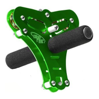
Trolley Components (Common to many models):
- Frame: Available in Red, Gold, Purple, or Blue.
- Sheave Assembly: Includes two .040 Wide Sheaves, four Bearing Spacers, and four R4 Bearings.
- Handle Assembly: Includes a Handle, two Handle End Caps, and two Foam Grips.
- Brake Assembly (Optional Kit): Includes a Brake Pad Holder, Brake Pad, Trigger Screw, three Trigger/Spacers, a Nut, two Brake Return O-Rings, and two Grooveless Retainers.
- Tow Rope Assembly: Included for launching riders.
- CD (Discontinued): A component that is no longer included.
- Frame Screws/Nuts/Spacers: Used for assembly.
Flexible Seat Assembly:
- Seat: Yellow.
- Webbing: 8 Ft. long.
- Tri Glide: 1 In. (2 needed).
Disc Seat (Trolley W/Disc Seat model):
- Blue Disc Seat: A specific seat type for certain trolley models.
- Washer: Used with the disc seat.
- Webbing: Used to attach the disc seat.
Usage Features
Installation Process:
- Site Selection: Choose a straight, clear path between two appropriately sized trees (8-10 inches+ diameter). Avoid obstructions, electrical wires, roads, or ravines.
- Cable Measurement: Determine cable length, adding extra for loops around anchor trees and a safety link.
- High End Anchor: Create a loop with a thimble and three clamps on one end of the cable. Nail 2-inch thick wooden blocks around the higher anchor tree (8-12 feet high) to protect the tree and hold the cable. Wrap the cable around the tree and blocks, slipping it through the loop.
- Trolley Installation: Slip the cable through the trolley's pulley. For existing zip lines, the trolley can be installed by removing and re-installing lower screws, nuts, spacers, and the trigger bolt (if brakes are present).
- Lower End Anchor: Determine the height for the lower anchor sling (6-8 feet high). Create a sling with loops on each end (using thimbles and three clamps). Wrap the sling around the lower tree.
- Tensioning: Attach a 2-ton come-along to the lower tree anchor loop. Create a loop on the zip line for the come-along hook. Tighten the cable using the come-along lever, then check all cable clamps for tightness.
- Safety Link: Install a safety link around the lower anchor tree, just below the anchor sling, and connect it to the zip line loop. This link is crucial for safety and must be kept tight.
- Stop Block: Install an optional stop block at the termination point. This device, attached to a shock cord or bungee cord, slows the rider to a stop.
- Final Assembly (Trolley): Thread seat kit webbing through the trolley and tri glide buckles. Tie the towrope to the spacer. Slide the T-bar through the trolley, then slide the foam grip onto the T-bar end.
Riding the Zip Line:
- Adult Supervision: Always use under adult supervision.
- Single Riders: Only one rider at a time. Do not ride double.
- Seated Riding: For seat models, always ride seated and hold onto the T-bar with both hands.
- Launching: Towing the rider to the top of the run using a towline is highly recommended to avoid the need for platforms or ladders.
- Seatless Trolleys: Exercise extreme care when using seatless trolleys. Design the line so that if the rider loses grip, the fall is only a few feet.
- No Jumping: Do not jump off the zip line while traveling.
- Safe Descent: Never set the cable rate of descent to unsafe angles or heights.
Maintenance Features
Pre-Use Inspection:
- Full System Check: Inspect the entire zip line system, including the pulley and sling, for any damage or wear before every use.
- Damaged System: DO NOT ride a system that is damaged.
- Safety Link Check: Ensure the safety link is always maintained and kept tight. NEVER use the zip line without a tight safety link.
Brake Pad Replacement:
- Remove Bolt: Remove the long bolt on the trigger.
- Remove Brake: Remove the brake from above.
- Remove Old Pad: Use a screwdriver to pop out the old pad.
- Install New Pad: Slip the new pad in.
- Replace Brake Unit: Reinstall the brake unit.
- Replace Bolt: Replace the long bolt.
General Maintenance:
- Cable Clamps: Periodically check all cable clamps for tightness, especially after initial tensioning and adjustments.
- Safety Link Adjustment: If any adjustments are made to the zip line, always readjust the safety link.
- Tree Protection: The wooden blocks used during installation protect the tree from cable damage.
- Professional Assistance: Seek competent local assistance if unsure about working with trees, cable installation, or maintenance.