HOW TO OPERATE
THE POWER
FEED
ATIGIII'
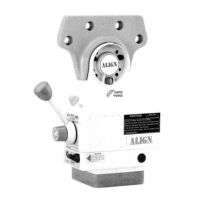
HOW TO INSTALL THE DRIVE
UNIT
1 Move the table to the
extreme
left-hand
position.
2 Slide the bearing face
onto
the lead-screw.
3 Slide the adaptor onto the bearing face.
4
Secure
it
to the end of the table with the existing cap-screws.
5. Slide the
power-feed
onto the bearrng-face.
6
Secure
it
to
the
adaptor
with
the cap-screw
provided.
HOW TO INSTALL THE BEVEL
GEAR
1
.
Press
and turn the bevel-gear
(Part
No. A-0100-03) manually
against the
gear (Part
No.
A-0106)
at the bottom of the
face
of
the
power-feed
and check the clearance
between
the two
parts
2 Leave the clearance
between
the two
as small as
possible,
if
there is some clearance
left,
put
the
shims one by one until
the
proper
clearance
rs
set.
HOW TO INSTALL THE DIAL
AND
THE
HANDCRANK
1 After
the
proper
backlash was set
(as
shown in the
sketch on
Page
2), adjust the dial
to obtain 0 005
spacing between
the
dial and the
face
of the
power-feed
to keep the
chips from entering the
gear
train
Use
the
two solid and two laminated
washers
pro-
vided to accomplish 0 005 spacing
Use also
the
shims as required.
2 ln the following
sequence,
put
on
the
dial
locking-nut,
place
key in shaft,
slide
the hand-
wheel in
place,
add the washer and locking-nut,
and tighten the
locking-nut.
HOW TO INSTALL THE LIMIT.SWITCH
1. Undo and remove the
standard
table
stop-pieces,
replace
them with the stop-pieces
provided
Put standard stops back in
position
to
prevent
feed-stops from
being set
beyond the extreme tabletravel.
2. Undo and remove the two
cap-screws
holding
the
T-shaped
table-stop bracket. Retain
it
to act as a
positive
stop Where required for manual
operation
3. Place the
short spacers
into
the counterbored
holes in
the
T-stop
and
place
the limit-
switch on the spacers and locate them on the table
using
two 3/8
-
16 x 1 inch
socket
head cap-screws.
4 Engage
the
limit-switch
(0,4)
inch
before the mechanical stop to allow for
coasting of
the table in
a
proper
operation Grind the
T-stops
to obtain
proper
operation if they are
not
symmetrical.
5. Secure the limit-switch cord using the
clamp
provided
Attach
it
to
the right-hand
side
of the chip scraper with the screw
provided.
MODEL
AL-235
NEW
AL-250
VoLTAGE
(ACtHZl
AC 110V 50t60HZ AC 110V 50/60H2
SPEED RANGE
0-140
B.P.M
0-200 R.P.M.
MAXIMUM
SPEED
200 R.P.M
200
R.P.M
FEATURES
BRAKE
DEVICE IN MOTOR
-1-
I
 Loading...